
Infrared Switch Circuit

The infrared-controlled switch circuit is designed for ease of use and versatility in controlling AC devices. The TSOP 1738 IR sensor is capable of receiving signals from standard remote controls, making it a practical choice for home automation applications. The output behavior of the CD4538 IC, configured as a monostable timer, allows for a reliable timing mechanism that can be adjusted based on the application requirements.
The circuit components include the TSOP 1738 IR sensor, the CD4538 IC, transistors T1 and T2, a relay, and the timing components R3 and C1. The choice of R3 and C1 values directly influences the timing duration, which is critical for ensuring that the load operates for the desired period. The relay acts as a switch for the AC load, providing isolation and safe control of higher voltage devices.
In practical applications, this circuit can be utilized for various purposes, such as controlling lamps, fans, or other household appliances remotely. The simple design and use of commonly available components make it an accessible project for electronics enthusiasts and professionals alike. Proper considerations for safety and compliance with electrical standards should be taken into account when implementing this circuit in real-world scenarios.A Simple Infrared controlled Switch. It can be operated using the TV remote handset. The Load can be any AC operated device which can be connected to the relay. The load turns on for three minutes then goes off. It can be used to switch on the lamp in the TV room The circuit uses the popular IR sensor module TSOP 1738 and the precision Mono stable / Astable IC CD4538. TSOP 1738 IR sensor accepts 38 KHz infrared pulses from the remote. Its output is high at power on and gives 5 volts. When it senses pulsed IR rays, its output becomes low. CD4538 is the Precision Monostable /Astable Multivibrator IC that is free from false triggering. It is more reliable than the popular timer IC 555. Here the IC1 is wired as a short duration monostable timer using R3 and C1 as timing components. With the given values, output of IC1 remains low for three minutes. By changing the value of C1 or R3 various time intervals can be obtained. Unlike 555 IC in the monostable mode, here in CD4530, output of IC becomes high at power on and becomes low when the trigger pin5 gets a low-to-high transition pulse. Normally, the output of the IR sensor remains high and T1 conducts. This keeps the trigger pin 5 of IC1 low. When the remote handset is focused on to the IR sensor and any of the button is pressed, output of IR sensor becomes low and T1 turns off.
This makes the collector of T1 high and the low to high transition at pin 5 of IC1 triggers it and its output becomes high. T2 then turns on and relay triggers. The load connected between the common and NO contacts of the relay turns on for three minutes. Adjust VR to keep IC2 off in standby condition 🔗 External reference
Related Circuits
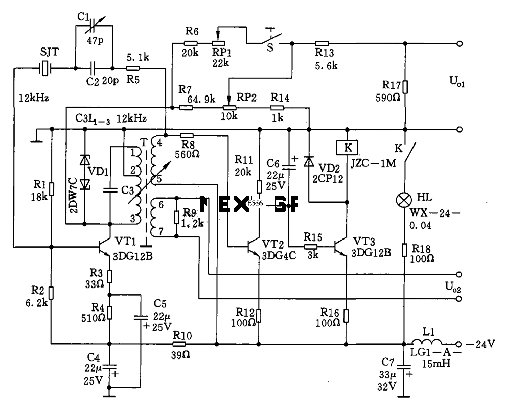
The circuit features a 12kHz intermediate frequency (IF) oscillator utilizing a quartz crystal for precision frequency generation. It includes components for output level adjustment, a level-up circuit, and an alarm circuit. The design employs a unique single-tuned variable feedback...
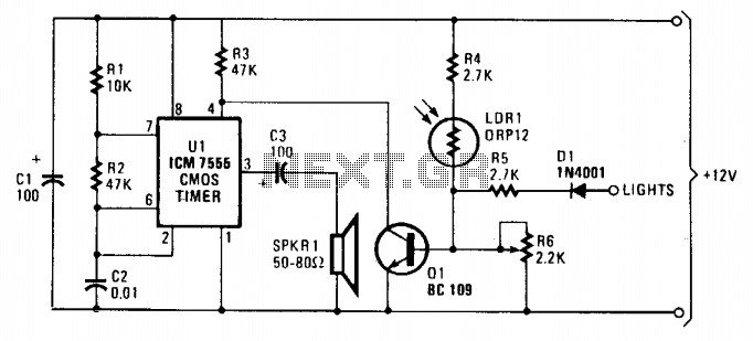
As dusk begins to fall, the sensor, which is a cadmium-sulfide light-dependent resistor (LDR), activates a small horn to provide an audible reminder to turn on the lights. The circuit can be turned off by simply switching on the...
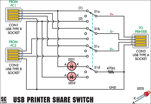
This simple device enables two computers to share a single USB printer or other USB devices, such as an external flash drive, memory card reader, or scanner. A rotary switch is used to select the PC that will be connected...

The STANDBY/ON switch is suitable for applications such as industrial and telecom, where the circuitry needs to retain its state (either STANDBY or ON). The STANDBY/ON switch circuit is designed to maintain the operational state of the system, ensuring that...
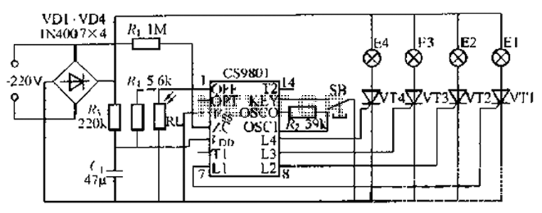
The ASIC is a flashing light string controller featuring four outputs. It includes a single key cycle control with six different lighting effects, and it allows for the selection of either 16 or 8 patterns. The circuit incorporates a...
A recent thrift shopping experience revealed a toy that appears to be suitable for circuit bending. The toy was found without batteries, preventing any testing at the store. It may be beneficial to bring batteries during future visits or...