Four flashing lights string circuit 4
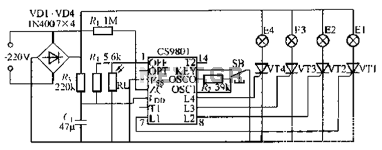
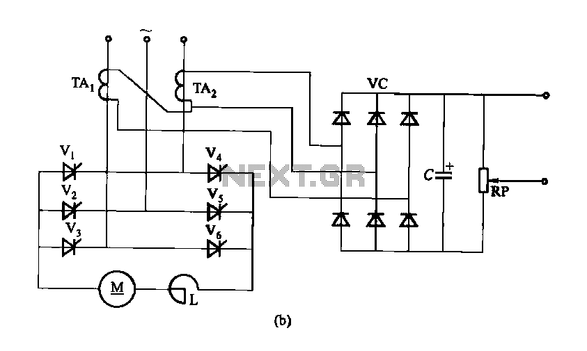
The ASIC is a flashing light string controller featuring four outputs. It includes a single key cycle control with six different lighting effects, and it allows for the selection of either 16 or 8 patterns. The circuit incorporates a photosensitive resistor (R1), enabling the string lights to automatically turn off during the day and flash at night. This circuit is particularly suitable for Christmas lighting. The product circuit adheres to the DIJrJ-I-1 standard packages, which can also be customized, including options for black soft cream packaging based on customer requirements. The power supply voltage range is from 2 to 7V. The output from the chip (1.1-1.4) can directly drive a thyristor. The key input (KEY) allows each button press to change the color cycling pattern, with a total of 16 patterns available, as indicated in Table 82. The circuit (CS98) has a vacant end (PT 1) that can automatically cycle through the 16 patterns. Each button (SL3) can change the lantern string patterns (E1-E4) as shown in Table 82. An optional MC45 type photosensitive resistor can be used, which will deactivate all lights during the daytime. The thyristor (cho MC) and resistor (R100-8 type) must be selected based on the AC electrical specifications. For a 110V, 60Hz AC network, a recommended resistor value of 25-33kΩ is suggested, with a second recommended value of 68-150kΩ. For a 220V, 50Hz AC grid, a recommended resistor value of 33-39kΩ is advised, with an additional recommended value of 50-300kΩ.
The ASIC flashing light string controller is designed to provide versatile lighting effects suitable for festive occasions, particularly during Christmas. The functionality of the controller is enhanced by its ability to cycle through various patterns, which can be easily selected using a single key input. The incorporation of a photosensitive resistor allows for automatic operation, ensuring that the lights are only active during the night, thus conserving energy and prolonging the lifespan of the lighting system.
The circuit is designed to operate within a power supply voltage range of 2 to 7V, making it adaptable for various low-voltage applications. The direct drive capability of the thyristor from the chip output simplifies the design by reducing the need for additional driving circuitry. The user interface is intuitive, with the key input allowing for easy cycling through the different lighting patterns, making it user-friendly for various applications.
The recommended resistor values for both 110V and 220V AC networks are crucial for ensuring the circuit operates safely and effectively under different electrical conditions. The selection of appropriate resistors will mitigate risks associated with overcurrent and ensure stable performance of the thyristor. This adaptability to different voltage levels makes the ASIC controller a versatile solution for decorative lighting, accommodating a range of installation scenarios and user preferences. By ASIC it is a flashing light string web dig troller, which has four outputs; single key cycle Control 1 6 kinds of tricks, and can choose 16 or section 8 before paragraph aft er paragraph 8 pattern. Electrical circuit further has a photosensitive resistor R1., Can string lights automatically turn off during the day, night flashes; the circuit is very suitable for Christmas. producing product circuit DIJrJ-I-1 standard packages can also be customized and then seek black soft cream packaging according to customer use the power supply voltage range of 2-7V.
1,1-1,4 chip output can directly drive a thyristor, KEY is the key input, each button can be changed once a color Chan circulation pattern, Jt has 16 patterns, as shown in Table 82: The circuit CS98. () PT 1 vacant end, it can automatically cycle 16 kinds of patterns, each button SL3 - times lantern string El- E4 press changes shown in table 82, s optional MC; 45 type photosensitive resistor, during the day can since moving to close all lights extinguished.
Thyristor-cho MC, R100-8 type. Vibration resistance R: current limiting buck hurricane resistance should make the necessary changes according to the AC electrical Ju A and L frequency size, when the state 110V, 60Hz AC network when, R. The recommended value 25-33kn:. R recommended value 68-150kfl. When using 220V,/50Hz AC the grid, R. The recommended value 33-39kfl; R. The recommended value] 50-300kn.
