
1W Linear FM Booster

The RF amplifier described is designed for enhancing the signal strength of small FM transmitters and similar devices, commonly referred to as "bugs." The circuit utilizes two Philips 2N4427 transistors, which are known for their high frequency and power handling capabilities. The amplifier is rated at approximately 1 Watt output power, making it suitable for driving linear amplifiers like the BGY133 or BLY87, which can further increase the output power to meet specific transmission needs.
The power supply requirements for this amplifier are critical; it must provide a current of 500 mA at a nominal voltage of 12 Volts. While increasing the supply voltage can enhance the transmission range, caution is advised as exceeding 15 Volts can lead to overheating and premature failure of the transistors. Therefore, maintaining the voltage within the specified range is essential for reliable operation.
The amplifier is optimized for operation within the frequency range of 80 MHz to 110 MHz, providing a gain of 15 dB in this bandwidth. This characteristic makes it effective for FM broadcasting applications. The design includes three inductors, L4, L5, and L6, which are constructed as air coils with a diameter of 5 mm and consist of 8 turns of 1 mm diameter wire. These coils are integral to the tuning and stability of the amplifier, ensuring efficient signal amplification.
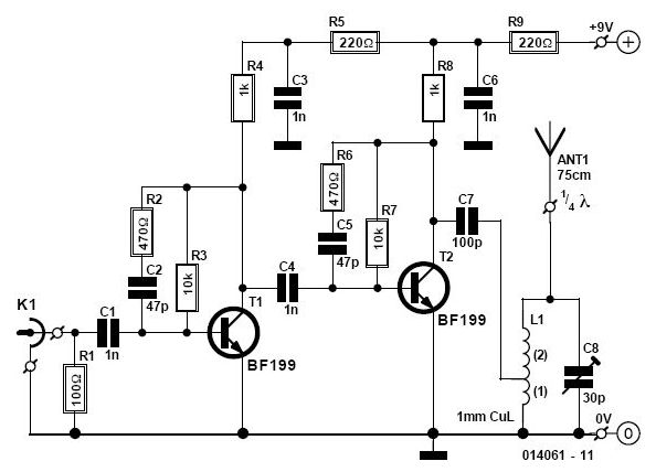
Overall, this RF amplifier design is straightforward and yields significant results, making it an attractive project for hobbyists and professionals looking to enhance their FM transmission capabilities. Proper assembly and adherence to the specified voltage and current parameters will ensure optimal performance and longevity of the circuit.That RF Amplifier is for boosting small fm transmitters and bugs. It use two Philips 2N4427 and its power is about 1Watt. At the output you can drive any linear with BGY133 or BLY87 and so on. Its power supply has to give 500mA current at 12 Volts. More voltage can boost the distance but the transistors will be burned much earlier than usual.! In any case do not exceed the 15Volts.
The Amp offers 15 dB in the area of 80Mhz to 110 Mhz. L4, L5, and L6 are 5mm diameter air coils, 8 turns, with wire 1mm wire diameter.An easy project, with great results.
Related Circuits
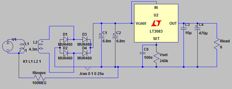
Additionally, it may be necessary to include another input capacitor to mitigate high-frequency noise, although this is not directly related to the main question. The objectives are to achieve a voltage output of 0 - 12 V with a...
The presented design features an unconventional arrangement that provides certain advantages compared to traditional designs. To begin with, a linear power supply incorporates a transformer that steps down the line voltage to a level higher than the regulated output...
Although the output is low-level and cannot be significantly loaded without compromising accuracy, a single integrated circuit (I.C.) operational or instrumentation amplifier can provide both linear gain and buffering for various loads. The minimum parts count version of this...
This circuit enables the use of a portable VHF FM radio to receive audio from stations that exclusively broadcast on the local cable network. This circuit operates by modulating the audio signals from the local cable network onto a carrier...
This project was a surprise as the BC547 transistor (equivalent to 2N2222) can be used to construct a 500mW linear amplifier that operates across the entire HF band with excellent spectral purity and without the need for neutralization. The...
The SP1481E, SP1485E, SP1490E, and SP1491E series transceivers, combined with the SP6652 high-efficiency, high-frequency current mode PWM buck regulator, facilitate the creation of an isolated RS-485 interface capable of providing up to 2kVrms isolation. This configuration supports CAN communication...