
Installing Bathroom Electrical Wiring

This circuit diagram provides a comprehensive overview of the electrical wiring necessary for a bathroom installation. It typically includes components such as lighting fixtures, outlets, and switches, all designed to meet safety standards and enhance energy efficiency.
Key features of the circuit include the use of GFCI (Ground Fault Circuit Interrupter) outlets, which are essential for bathroom environments due to the proximity to water sources. The GFCI outlets protect against electrical shock by interrupting the circuit when a ground fault is detected.
The circuit also incorporates energy-efficient lighting options, such as LED fixtures, which reduce overall power consumption while providing adequate illumination. The layout of the wiring should ensure that all fixtures and outlets are positioned for optimal functionality, taking into account the bathroom's design and usage.
In addition, the circuit should be designed to comply with local electrical codes, ensuring that all installations are safe and reliable. This includes proper grounding of all electrical components and the use of appropriate wire gauges based on the load requirements.
Overall, the bathroom electrical wiring circuit diagram serves as a vital tool for electricians and homeowners alike, facilitating a safe and efficient electrical system tailored for bathroom use.The following circuit shows about Installing Bathroom Electrical Wiring Circuit Diagram. Features: safety, energy saving, increase your home .. 🔗 External reference
Related Circuits

The circuit diagram for an electric start and stop timer is illustrated in the following cycle. It utilizes the LM555 integrated circuit configured as an adjustable duty cycle multivibrator. The circuit includes components C3, KH1, W1, KH2, and W2,...

It is advisable to obtain TIP41 and TIP42 transistors, which are closely matched NPN and PNP power transistors with dissipation ratings of 65 watts each. If a TIP41 NPN transistor is unavailable, the TIP3055 (available from Radio Shack) serves...
1990 Acura Integra Starting System Wiring Diagram. The 1990 Acura Integra starting system wiring diagram provides a visual representation of the electrical connections and components involved in the vehicle's starting system. This diagram is essential for understanding the layout and...

The circuit illustrated in Figure 3-151 consists of capacitor banks arranged in a specific configuration. Figure 3-151 (a) depicts capacitor banks connected in a shaped configuration, which is suitable for shaped or Y-connected motors. Figure 3-151 (b) shows Y-connected...
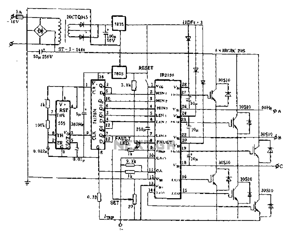
The application of the aforementioned advantages allows the IR2130 to be effectively utilized for DC cut crossing speed, DC servo systems, three-phase power inverters, and switching power supplies. Additionally, it is applicable in inverter power supplies, uninterruptible power supplies...

Afroman explains the fundamentals of transformer operation, where to purchase step-down mains transformers, and how to safely wire one to mains voltages. The discussion includes both European and North American wiring standards. The presentation concludes with a brief example...