
instructions to assemble energy

The subsequent instructions primarily derive from the experimental work of Jean Louis Naudin, particularly versions 3.2 and 3.3. It is important to note that the current realization of version 3.3 of the Kapanadze device by Jean Louis Naudin has not yielded output power exceeding the input power. This contrasts with Kapanadze's original work. The details of the v3.3 realization are shared due to the lack of detailed successful implementations, aside from possibly the contributions of Andre Fabrice. Despite this, some experimenters reported achieving output power greater than the input power. For instance, one experimenter, Robert, succeeded in obtaining 1800W output relative to an 800W input, following persistent experimentation, which included changing the diode and utilizing a coil with three segments of different turn counts (22-84-6) in contrast to the current version 3.3.
Another notable experimenter, Romerouk, also reported achieving greater output power than input power in his replications of versions 1.1 and 1.2 of the Kapanadze device. It is essential to mention that Naudin's instructions do not explicitly indicate the winding direction (clockwise or counterclockwise) for the coils, nor their arrangement on the tube. Despite this omission, it has been observed that he was unable to achieve output power exceeding input power. Videos by amateurs who have successfully constructed Kapanadze-like devices typically utilize three coils arranged in a cylindrical configuration rather than just two. The circuit connections proposed in one such video are claimed to be the only configuration that enables the device to function correctly, preventing the coils from canceling each other's effects.
According to the orientations of the coils and the circuit connections suggested by the amateur, the configuration resembles that of a transformer. In this setup, the primary coils (22 turns and 84 turns) receive a high voltage non-DC current, while the secondary coil (6 or 9 turns) provides an output current with additional energy. Both the primary and secondary coils share a common grounding pole. This configuration results in two unequal magnetic fields from the coils, with opposite (repelling) orientations of their north and south poles.Free-energy" or "G-solar energy" as solar infrared radiation energy stored in the gravitational field. Alternative terms: "Aether heat", "2nd-material layer Heat" In the link below, professor KonstantinMeyldescribes in detail simple experimental setting of miniature Tesla towers in University laboratory, so as to measure beyond doubt the free-energy.
He also proves the existence of scalar (non-vector or non-Herz) ) waves of the electromagnetised aether (I assume them to be scalar waves of the scalar electromagnetic potential). In neutral aether, such waves would be the aether sound compression waves (travelling of course at the speed around that of light, or in cases that molecular mater is present maybe faster than light).
This professor has published papers, and books about his findings, and has developped his own unified-field theory. And what is also practical, he has designed and sells, experimental kits (for about 300 euros) of miniatures of the Tesla-towers, where he measures in the receiver tower 4 times more power (in milli-volts), as "free energy".
B) The next set of instructions is taken mainly from the experimental work of the laboratory of Jean Louis Naudin. ( ) and in particular version 3. 2 and 3. 3. We must notice inadvance, that the present realization v3. 3 of the Kapanadze device, byJean Louis Naudin, is so that the device fails, in the sense, that it does not give more power, that the given input power.
But this is not what Kapanadze did. I only give the details of v3. 3 realization by J. L. Naudin, because I know of no other very detailed data of realization that did succeed (except perhaps the next video by Andre Fabrice, and more material here ). Nevertheless, as J. L. Naudin has published in the same page, of his site, some of the experimenters claim that they did get more output power than the input power.
E. g. the exprimenter Robert below, (# 10 - June 21, 2010), did succeed, to have more power at the output (1800W) relative to the input power (800W). But this only after persistingexperimentation, after changing the diode with another, and his coil too has three parts of different number of turns (22-84-6) that the current version v3.
3. It seems also that the experimenterRomerouk (# 3 - June 10, 2010 - Kapagen replication v1. 1 and 1. 2 ) didsucceedto have more outputpowerthat inputpower. Another important remark is that the instructions of J. L. Naudin, in his site do not specify explicitly the clockwise or counterclockwise winding of the three or two parts of the coils, and the placing of them on the tube. But even if he did we know that he failed to get more power as output than as input. The next video is from an amateur who doescarefullyspecifies, the directions of the turns of the three coils and gives also a slightly different circuit diagram.
In all videos that I am aware that havesuccessfullyrealized a Kapagen-like device, where they get more power as output than as input, do utilize three coils in thecylinderconfigurationof coils and not only two. The circuit connections of the last video above, are claimed by the amateur that are the only that make it work, and not have the coils cancel out the their effects.
We may notice that according to theorientationsclockwise/counterclockwise on the geometry of the three coils, and after the circuit connections that the previous amateur proposes with a grounding connected in between the three coils, it seems as if he is having the nextconfiguration: a transformer, that in its primary part (coils 22 turns/84 turns) it is given a high voltage non-DC current, and so that the secondary part (coil 6 or 9 turns) gives the output current with extra energy, and both primary and secondary have a common pole in the grounding. The above configuration is so that there are two non-equal magnetic fields from the coils withopposite(repelling) position of their north and south poles.
Such a configurati 🔗 External reference
Related Circuits
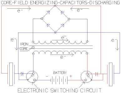
The fundamental concept involves a high-frequency, high-voltage, low-current signal that is rectified and subsequently utilized to charge a bank of high-value capacitors. These capacitors are then discharged in pulse mode for brief intervals, specifically in the nanosecond range, through...

A thorough examination of the Kapanadze video reveals that the vertical coil is wound with copper tape, forming a capacitor that captures environmental particles with the assistance of high voltage. Experiments indicate that it charges easily with minimal power...
This sensitive circuit functions primarily as a comparator, capable of detecting minimal temperature changes relative to ambient temperature. It was originally designed to identify drafts around doors and windows that lead to energy loss, but it can be utilized...
A Georgia Republic inventor, Tariel Kapanadze, claims to have invented a 5 kilowatt free energy generator. In a demonstration video, the device appears to produce copious amounts of energy from no visible source. More: The components apparently include a...
so what happens when you flip a switch? When you try to stop the flow of current in 'zero' time its equivalent to trying to stop a freight train instantaneously. you get a huge voltage buildup "dv/dt" = "X/0=infinity...
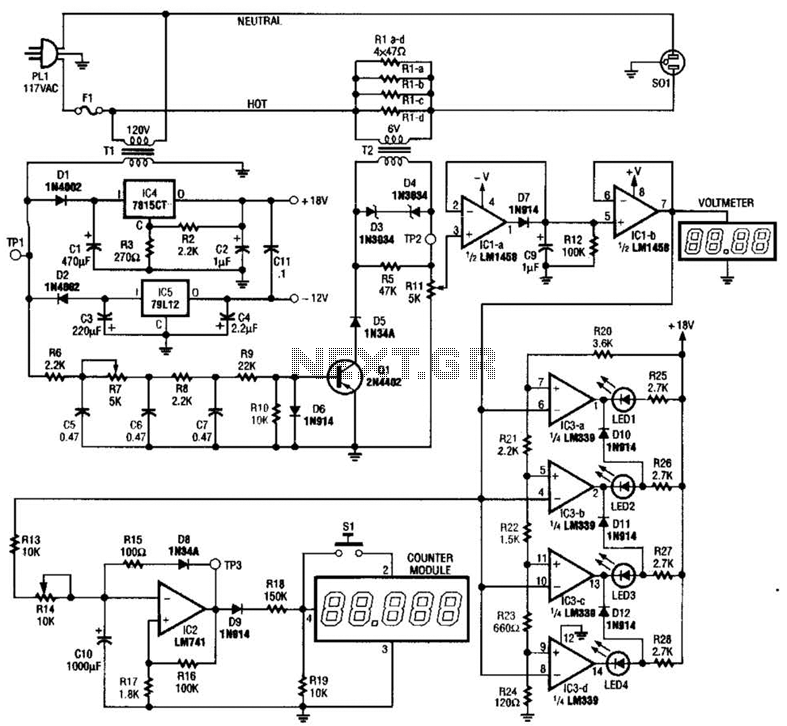
The ECM circuit comprises four sections, as illustrated in the block diagram. A power converter generates a voltage that correlates with the actual real power consumed by the load. This voltage supplies both a bar graph and a voltage-to-pulse...