
Instrument preamp

The circuit described involves an operational amplifier configured for feedback with a tone control feature that enhances the audio output. The input impedance is determined by the potentiometer Rl, allowing for adjustments based on the connected load or desired sensitivity. The choice of capacitor C1 is critical; a reduction to 0.5 mF is suggested for instruments with pronounced deep bass to avoid overwhelming the audio output.
The feedback loop is essential for maintaining stability and defining the gain of the circuit. Resistor R7 plays a pivotal role in this feedback mechanism, while the combination of resistor R4 and capacitor C3 is responsible for setting the voltage gain to approximately 14 dB. This gain is significant as it amplifies the input signal, providing a robust output suitable for various audio applications.
For fine-tuning the bass response, capacitor C3's value can be adjusted. Increasing its capacitance from an initial 1 µF to a maximum of 10 µF allows for enhanced low-frequency performance. This adjustment should be made incrementally, observing the output to achieve the preferred bass characteristics. The overall design emphasizes flexibility and adaptability to varying audio requirements, making it suitable for a range of electronic audio devices.The input impedance is the value of potentiometer Rl. If your instrument has extra-deep bass, change capacitor Cl to 0.5 mF. What appears to be an extra part in the feedback loop is a brightening tone control. The basic feedback from the op amp's output (pin 6) to the inverting input (pin 2) consists of resistor R7, and the series connection of resistor R4 and capacitor C3, which produce a voltage gain of almost 5 (almost 14 dB). That should be more extra oomph than usually needed. If the circuit is somewhat short on bass response, increase the value of capacitor C3 to 1 to 10 µ. Start with 1 µ¥ and increase the value until you get the bass effect you want.
Related Circuits
The schematic in question pertains to a phono preamplifier that is characterized by an accurate RIAA equalisation curve. Notably, this preamplifier boasts superior sonic performance compared to most others featured in magazines and application notes. This preamplifier, much like other...
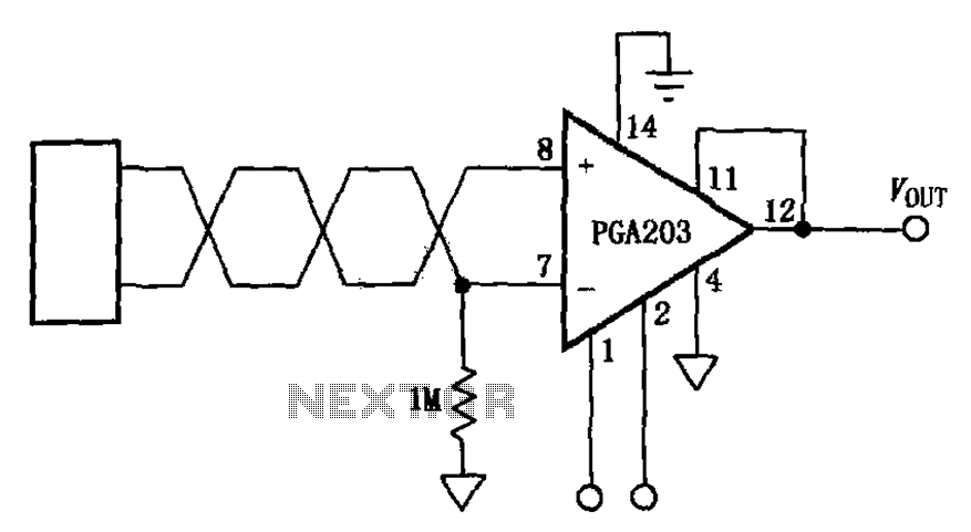
The circuit features a PGA203 programmable instrumentation amplifier. The input signal is applied to the twisted pair inputs of the PGA203, which subsequently amplifies the output signal. It is important to note that the input pins of the PGA203...
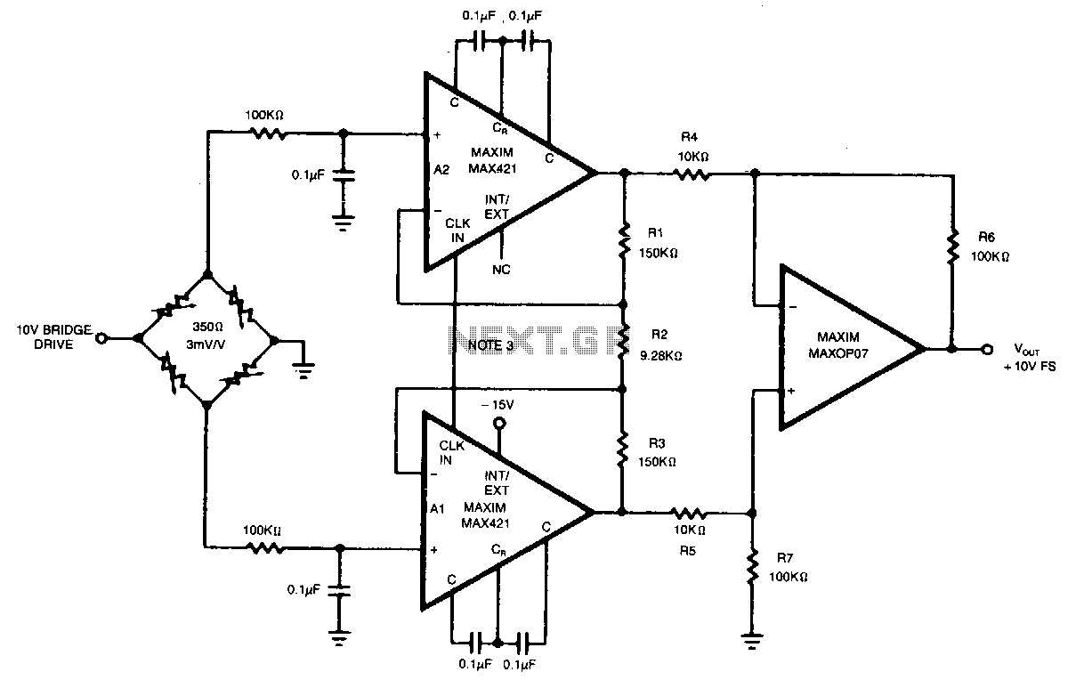
This circuit achieves an overall gain of 320. Additional gain can be obtained by decreasing the value of R2. The untrimmed Vas is 10.11V, and the Vas temperature coefficient is less than 0.1µV/°C. In various applications, the OP07 can...
This project originated from a design requirement for a client, specifically for a microphone preamplifier intended for basic public address (PA) systems. The simplicity of this circuit makes it suitable for various applications where a mic preamp is needed,...
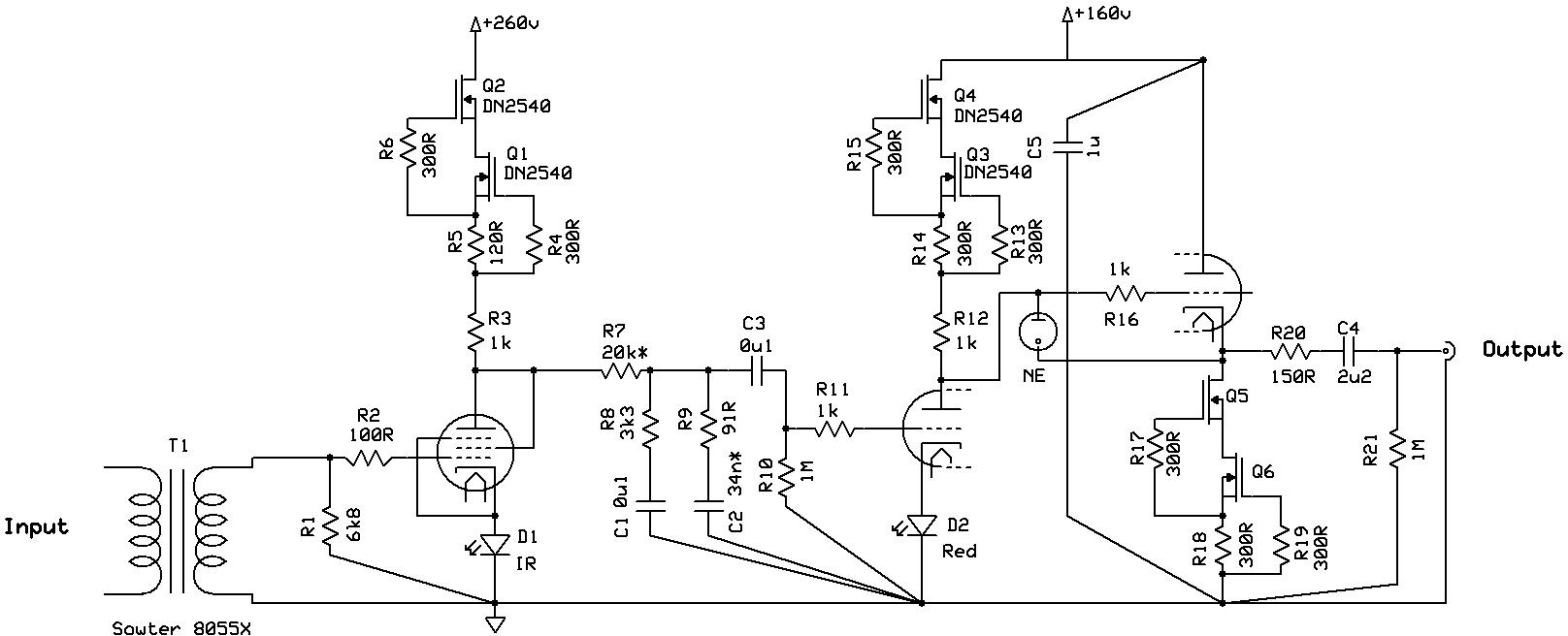
Even if it was not read thoroughly, it is a nice design with almost enough transformers, but certainly not enough shunt regulators. The circuit design under consideration features a configuration that includes several transformers, which are essential for voltage transformation...
This microphone preamplifier utilizes the low-noise integrated circuit (IC) uA739. It serves as a practical example of designing an effective preamplifier for dynamic microphones. The IC contains two identical integrated preamplifier circuits, with the second preamp functioning in the...