
Dynamic mic preamplifier circuit

This microphone preamplifier circuit is designed to enhance the audio signal captured by dynamic microphones, ensuring high fidelity and low noise levels. The uA739 integrated circuit is chosen for its low noise characteristics, making it ideal for audio applications where clarity is paramount. The dual preamp configuration allows for stereo microphone setups, providing a balanced audio input for both channels.
The voltage divider formed by R1 and R4 ensures that the non-inverting input is properly biased, which is critical for maintaining linearity in the amplifier's response. This biasing technique helps in achieving a stable operating point, which is essential for minimizing distortion in the output signal.
The RC filtering circuit, consisting of R3 and C4, effectively suppresses high-frequency noise that may be picked up by the microphone, thereby enhancing the overall signal quality. Additionally, the frequency compensation circuit formed by R7 and C6 prevents oscillations that could occur at high gain settings. This is particularly important in audio applications where unwanted feedback can lead to undesirable sound artifacts.
With an input impedance of approximately 47 kΩ, the preamp is well-suited for dynamic microphones, which typically have lower output impedances. This impedance matching is crucial for maximizing signal transfer and ensuring that the microphone's output is effectively amplified without loss of quality.
The output impedance of several hundred ohms allows for compatibility with a variety of audio processing equipment, ensuring versatility in different setups. The specified maximum peak-to-peak output voltage indicates that the circuit can handle audio signals without clipping, maintaining the integrity of the sound.
The frequency response of 20 Hz to 20 kHz covers the full range of human hearing, making it suitable for a wide array of audio applications. The optional high cutoff frequency of 80 kHz provides additional flexibility for specialized applications where higher frequencies may be relevant.
The ability to replace the uA739 with other ICs like TBA231 or SN76131 without modifying the external circuit design offers further convenience for engineers and designers, allowing for component substitution based on availability or specific performance characteristics desired. Overall, this microphone preamp design exemplifies a robust solution for high-quality audio signal amplification.This mic preamp uses the low noise IC uA739. The circuit is an example of how a good preamplifier can be designed for dynamic microphones. The IC houses two identical integrated preamp circuits. The second preamp is used in identical manner This mic preamp uses the low noise IC uA739. The circuit is an example of how a good preamplifier ca n be designed for dynamic microphones. The IC houses two identical integrated preamp circuits. The second preamp is used in identical manner for the second channel of the stereo microphone. The non-inverting input is biased at about 50% of the power supply. This bias voltage is set by the voltage divider circuit R1 and R4. The point between R1 and R4 is used commonly for both channels. The unwanted HF signals coming from the microphone are filtered out by the RC-circuit composed of R3/C4. Frequency compensation is done by the R7/C6 circuit. The values of R7 and C6 were designed to avoid oscillation at the amplification level of 100. The input impedance is about 47K. This means that a normal dynamic microphone gets connected to a high impedance preamp which in turn produces good results.
The output impedance is about several hundred ohms. THe maximum peak-peak output voltage is about several volts lower than the supplied power. The frequency range is from 20Hz to 20KHz (-3dB). The upper cutoff frequency is 80KHz when the low-pass filter is removed from the circuit. The IC shown can be replaced with TBA231 or SN76131 without changind the external circuit. 🔗 External reference
Related Circuits
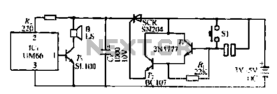
A few custom integrated circuits began to play music. When the song ends, no electricity flows through the thyristor, which then cuts off the light, causing the phototransistor to activate. The system is designed with a touchpad; each touch...
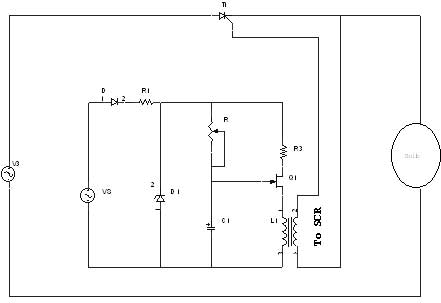
A unijunction transistor (UJT) is an electronic semiconductor device characterized by a single junction. It consists of three terminals: an emitter (E) and two bases (B1 and B2). The base is constructed from a lightly doped n-type silicon bar,...
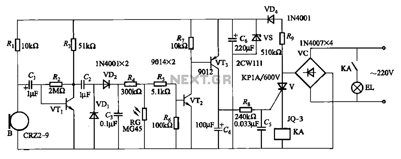
A resistor R8, capacitors Cd, and a thyristor V AC switch form a delay circuit. The lamp's lighting delay time is determined by the resistor Rs and capacitor C4, with a delay of approximately 40 seconds as indicated in...
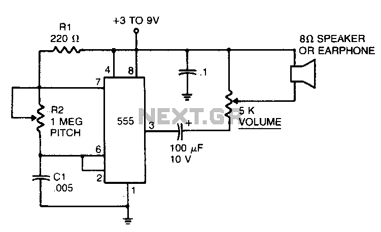
In the 555 oscillator circuit, adjusting R2 will provide output frequencies ranging from below 200 Hz to above 62 kHz. It is recommended to use a good quality miniature speaker to produce frequencies around 20 kHz. The 555 oscillator circuit...

This smoke detector electronic project is designed using the LM1801 and common electronic components. The smoke detector circuit diagram does not utilize ionization detection, gas sensors, or optocouplers; instead, it employs two photoresistors (LDRs) and an LED. The circuit...
It is easy to miss the sound of a doorbell while watching TV. This circuit addresses the issue by providing a visual indication, such as a lamp or an LED. Connecting a lamp directly in parallel with the doorbell...