
intercom

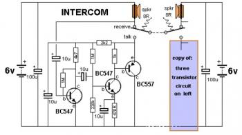
The intercom circuit is designed to facilitate two-way communication using standard audio components. The primary components include two speakers, a relay, a push-button switch, and a power supply.
In operation, the system begins with both speakers connected to the audio input. When the user presses the button, the relay is activated, which changes the connections of the speakers. This action allows one speaker to receive audio signals from the incoming communication while the other speaker captures sound from the user, effectively turning it into a microphone.
The relay used in this circuit is typically a double-pole double-throw (DPDT) type, which enables the simultaneous switching of both speaker connections. The power supply should provide adequate voltage and current to operate both the relay and the speakers without distortion or loss of audio quality.
To ensure optimal performance, it is essential to select speakers with compatible impedance ratings and a relay that can handle the audio signal levels without introducing noise. Additionally, proper wiring and grounding techniques should be employed to minimize interference and enhance audio clarity.
In summary, this intercom system represents a practical application of basic electronic components, allowing for effective communication through the innovative use of speaker functionality.This intercom uses an ordinary speaker to function as its microphone. Once the button is pressed, the relay toggles, and the speakers interchange their functions. One works as a normal speaker and the other one works as microphone. 🔗 External reference
Related Circuits
This is a two-station simple intercom circuit built using transistors and common 8-ohm mini speakers. The speaker functions as a microphone and generates sound, eliminating the need for a separate microphone in this intercom setup. The "press-to-talk" switches should...

This version of the intercom system is designed for users who require a reliable and affordable solution without access to an external telephone line. It is suitable for environments such as preschools, hobby farms, or small workshops, where it...
Tro telephones can be utilized as an intercom through the implementation of this circuit. Traditional rotary phones, particularly those that are non-electronic, may be the most effective for this purpose. Additionally, this method can also power handsets alone. The circuit...
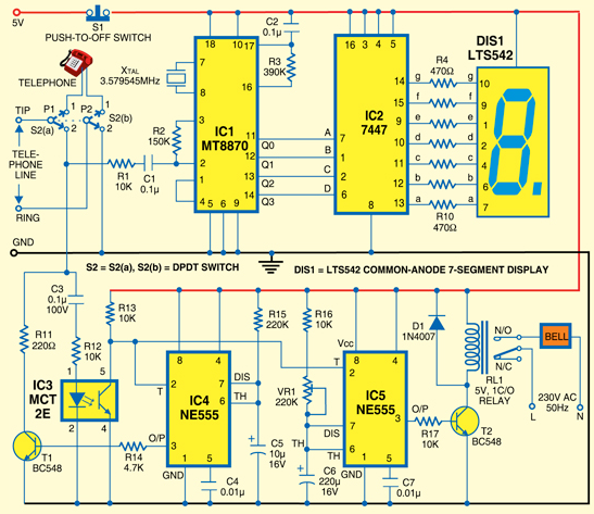
A simple calling bell circuit designed for small offices to summon the office boy using an existing intercom system. The office boy can be called from up to nine locations equipped with extension lines. The system connects to a...

The design consists of an amplifier, a double-pole changeover switch, and two loudspeakers: one for the master station and one for the slave. More than one slave unit can be used, but each requires an additional changeover switch. The...
A high-quality intercom system that can also be utilized for room monitoring. The intercom system described is designed to provide clear and reliable communication between different rooms or areas within a building. It features high-fidelity audio components that ensure minimal...