
Internal Intercom

The intercom circuit comprises several key components that facilitate its operation. The DTMF decoder (IC2) is pivotal for translating keypad input into a digital signal. This signal is processed by the 1 x 16 decoder (IC3), which controls the line relays (LR1 to LR4) via the driver and buffer transistors (Q1 to Q4). The Ring Trip Circuit (RTC) plays a critical role in managing the ringing state and ensuring that the call is connected once answered. The use of phototransistors, such as OC1, allows for effective feedback to reset the system after a call is completed, ensuring that the system is ready for subsequent calls. The design's simplicity, utilizing only two wires between handsets, enhances reliability and ease of installation, making it suitable for various applications where a robust intercom solution is required. The potential for additional control applications through unused outputs further extends the versatility of this intercom system.This version of the Link is for those who really need a good cheap intercom that will work reliably, but without access to an outside Telco line. This could be in a pre school, a hobby farm or a small workshop or factory, where external phone traffic needs to be kept separate and protected from phone abusers and kids playing aroundG It follow
s mainly the principals of the Link pulse dial circuit, but with the modifications and additions of the Link A2B+1 for DTMF dialing. Basically what IG ™ve done is remove the OSL relay and the flip flop (FF2) that controlled its activation and release, and added an extra two internal handsets and their associated relays and components.
FF1 (as part of the Ring Trip Circuit or RTC) is still there, but is now shown down the bottom of the diagram for simplicityG ™s sake. Internal wiring for the RTR relay is as per the Link A2B circuit. When any phone is picked up off hook and a number from 1 to 4 on the keypad is pressed, the DTMF decoder chip (IC2) decodes this into IC3 (1 x 16 decoder) and the output of IC3 is then fed to the appropriate base resistor of Q1 to Q4 (R11 through R14).
Pin 11 of IC3 goes low, removing the high from pins 12 and 8 of IC1 and impulsing of the selected line relay (LR1 to LR4) begins, via driver transistor Q5 and the appropriate buffer transistor (Q1 to Q4). When the called party answers the call, the RTC circuit G tripsG ™ the ring current, impulsing along with the ring tone is halted, and the conversation can proceed.
When the conversation is completed and both phones are hung up, the collector of OC1G ™s phototransistor goes high and resets both FF1 and IC3. Pin 11 of IC3 goes high again, halting the impulsing action of IC1 but providing dial tone from pin 5 in the reset state, ready for the next call.
One extra nifty little feature involves the # output (pin 14 of IC3). If you connect this to the set (S) input of FF1, you can halt the ringer if someone calls your extension while youG ™re away. You can pick up another extension anywhere else and press the # key and effectively G pick upG ™ the call.
This feature prevents the other phone from continuing to ring and also halts the ring tone from overpowering your conversation. In principal, it follows very closely the features of the Link pulse dialing version, except that thereG ™s only a two wire circuit between each handset and the G black boxG ™ switcher.
In reality, tone dialing is more efficient, and you could easily use some of the other unused outputs of IC3 for remote control purposes (turning on sprinklers or low voltage garden lights, door entry systems etc. ) 🔗 External reference
Related Circuits
A two-line intercom with a telephone changeover switch. This circuit can connect two telephones in parallel and function as a 2-line intercom. Typically, a single telephone is connected to a. The two-line intercom circuit is designed to facilitate communication between...
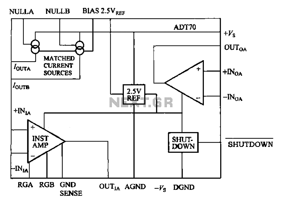
The ADI I70 is a signal conditioning integrated circuit designed for RTD/PRTD applications, particularly suitable for 1K and 100Ω platinum RTDs (PRTDs). The ADT70 features an integrated instrumentation amplifier, an operational amplifier, a 2.5V reference power supply, and a...

The circuit functions as a minimal component intercom system. When switch SI is set to the talk position, the speaker of the master station operates as the microphone with the assistance of step-up transformer T1. With a turns ratio...
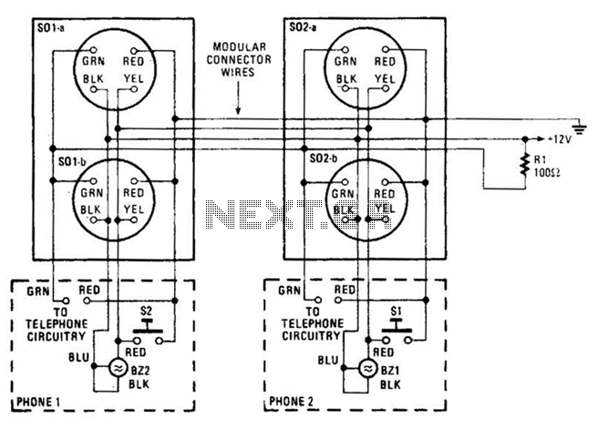
An intercom utilizing dual-modular wall jacks is depicted in this circuit. If the wires are accessible in the home telephone cable, this system can be installed with minimal difficulty. The intercom system described employs dual-modular wall jacks, which are standard...
A 567 IC tone decoder/detector can be utilized to construct a remote control or intercom system. This circuit is capable of controlling a relay or transmitting an audio signal. The 567 IC is a versatile integrated circuit designed for tone...
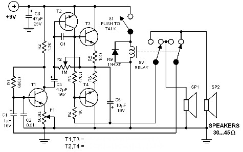
This intercom utilizes a standard speaker to operate as its microphone. When the button is pressed, the relay switches, allowing the speakers to exchange their roles. One speaker functions as a regular speaker while the other serves as the...