
intercom circuit using fader

The intercom circuit is structured to provide clear audio communication while allowing background music to be muted during conversation. The LM358 operational amplifier is central to the microphone amplification, ensuring that the audio signals from the electret microphones are adequately boosted for processing. The quad bilateral switch IC (4016 or 4066) enables seamless switching between the microphone inputs and the headphone outputs, facilitating user control over audio routing.
The design incorporates a volume control mechanism through R4, which not only adjusts the microphone sensitivity but also sets the muting threshold for the music playback. This feature is crucial in environments where background noise may interfere with spoken communication, allowing users to maintain clarity without constant manual adjustments.
The headphone amplifiers are optimized for low distortion, enabling high-quality audio output suitable for both speech and music. The transistors used in the circuit (BC560C, BC550C, BC337, and BC327) are selected for their low noise and high gain characteristics, contributing to the overall performance of the audio system. The careful selection of resistor and capacitor values allows for fine-tuning of the circuit's response to user preferences, ensuring a customizable experience.
Overall, the intercom circuit is designed for practicality and efficiency, making it suitable for various applications where audio communication is essential. The use of standard components and clear layout in the schematic facilitates easy assembly and troubleshooting, making this design accessible to both hobbyists and professionals in the field of electronics.This is a complete circuit that is shown in the diagram below and is formed by a microphone amplifier built around IC1A, is a design for intercom circuit. In this circuit, there are 2 IC, LM358 that is used to low power dual op amp and 4016 or 4066 Quad bilateral for switch IC.
This IC that is used to control the circuit. This is the figure of the circuit. The two microphones (small electret types) are connected to J1 and J2 and the two headphone sets (usually 32 Ohms impedance) to J4 and J5. The iPod headphone output is connected to J3 by means of suitable stereo cable and 3mm jack plugs. R4 acts as a volume control for the microphones and also sets the threshold at which the music will be muted: it should be set once for all and then left alone.
When speaking is stopped, the music will revert to full volume after some time-delay, set by R12 and C6. The value of these components can be varied to suit one`s own needs. The headphone amplifiers, despite the high number of transistors used, are simple enough, efficient and, above all, setup-free.
They are able to deliver a full 5V peak-to-peak sinewave into 16 Ohm (i. e. about 200mW into two 32 Ohm headphones wired in parallel) with less than 1% distortion @ 1KHz and 0. 7% @ 10KHz. At the standard 40mW headphone power output capability, distortion figures are 0. 6% @ 1KHz and 0. 3% @ 10KHz. R1, R2_22K 1/4W Resistor R3, R20_1K 1/4W Resistors R4_50K 1/2W Trimmer Cermet or Carbon R5_47K 1/4W Resistor R6, R7, R8_100K 1/4W Resistors R9, R10_68K 1/4W Resistors (See Comments) R11, R15, R16_1M 1/4W Resistors R12_470K 1/4W Resistor (See Comments) R13, R14_220K 1/4W Resistors R17, R18_100K 1/4W Resistors R19_470R 1/4W Resistor C1, C2, C5, C7, C8_100nF 63V Polyester or Ceramic Capacitors C3_100nF 63V Polyester or Ceramic Capacitor (See Notes) C4, C6_10 µF 25V Electrolytic Capacitors C9_100 µF 25V Electrolytic Capacitor C10_220 µF 25V Electrolytic Capacitor C11_470 µF 25V Electrolytic Capacitor D1, D2_1N4148 75V 150mA Diodes Q1_BC560C 45V 100mA Low noise High gain PNP Transistor Q2_BC550C 45V 100mA Low noise High gain NPN Transistor Q3, Q6_BC337 45V 800mA NPN Transistors Q4, Q5_BC327 45V 800mA PNP Transistors IC1_LM358 Low Power Dual Op-amp IC2_4016 or 4066 Quad bilateral switch IC J1, J2_3mm Mono Jack sockets J3, J4, J5_3mm Stereo Jack sockets SW1_SPST Toggle or Slider Switch B1_6V Battery (4 x AA or AAA 1. 5V Cells in series or any 6V rechargeable battery pack etc. ) 🔗 External reference
Related Circuits
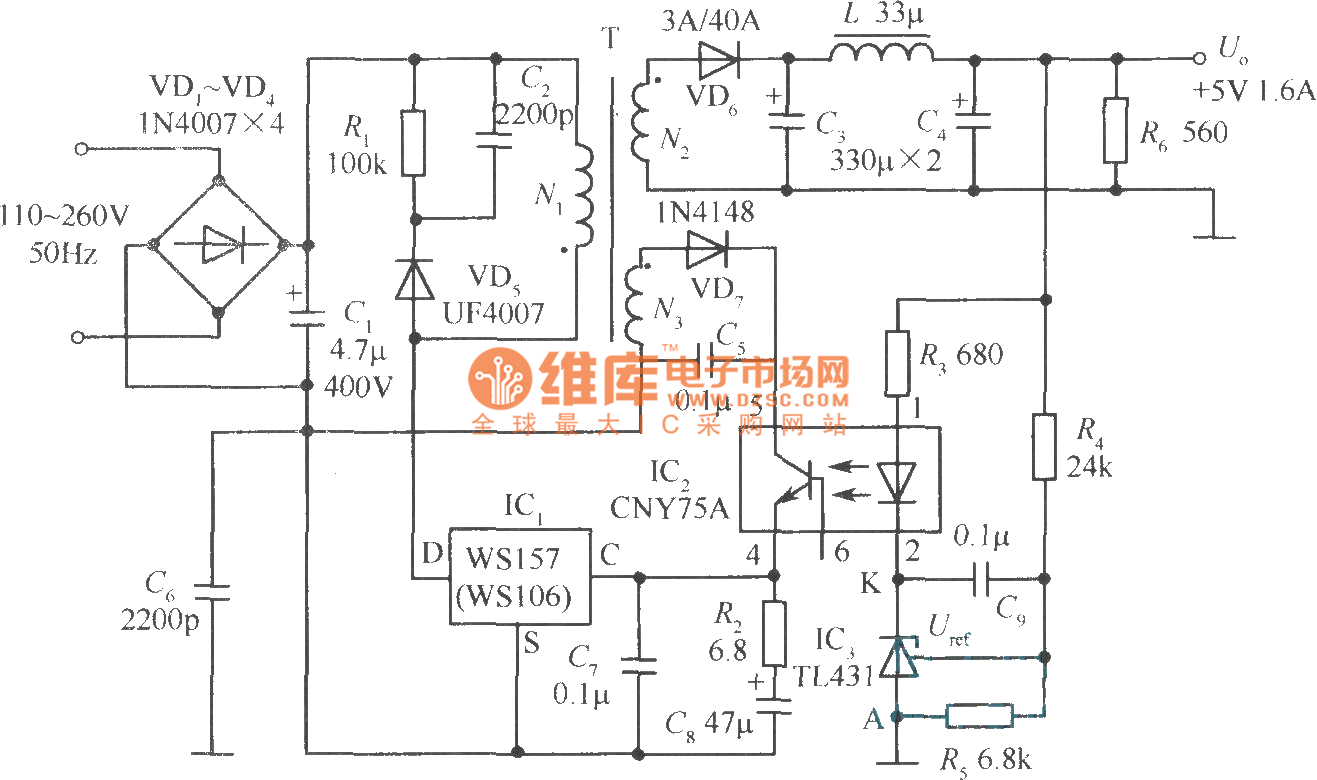
The +5V, 1.6A precision switching power supply circuit is depicted in the figure. This circuit utilizes a photoelectric coupler (CNY75A) and an adjustable precision parallel regulator (TIA31). R3 serves as the current limiting resistor, while R4 and R5 function...
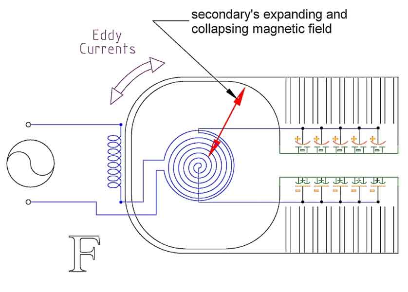
Arcing completes a circuit -- closes a system -- between two voltage potentials. When arcing occurs, two oppositely charged static voltage potentials can cancel each other out. The arcing problems that occur are usually between two electrically isolated voltage...
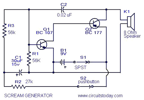
Multi Tone Alarm Description This is a simple and easy-to-build multi-tone alarm circuit that can be used in burglar alarms or sirens. The circuit is based on the dual op-amp MC1458 and LM380. The two op-amps inside the MC1458...
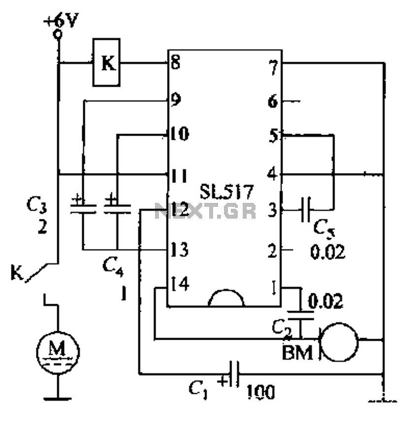
Electric cars utilize a voice circuit principle, where sound signals are captured by a microphone (BM) and processed. The signal is then coupled through a capacitor to an integrated circuit (IC), which includes an internal amplifier that boosts the...
AM radio receivers demodulate amplitude-modulated (AM) signals. The primary source of these signals is the Standard AM Radio Broadcast Band, although shortwave stations also utilize AM modulation. Amplitude modulation was developed between 1900 and 1917 by amateur radio enthusiasts....
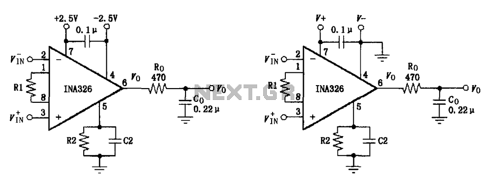
The basic connection circuit for the INA326/327 includes signals and power. A 0.1 µF capacitor is selected for power supply filtering and should be placed as close to the chip's supply pin as possible. Ro and Co serve as...