
intercom circuit using lm386 ic

The intercom circuit is designed to facilitate two-way audio communication, making it suitable for various applications such as home intercom systems, communication between rooms, or even as a basic intercom for small offices. The LM386 serves as the audio amplifier, providing sufficient gain to ensure clear sound transmission. The choice of an 8-ohm speaker is integral, as it ensures compatibility with the LM386, which can drive low-impedance loads effectively.
The 10K variable resistor functions as a volume control, allowing users to adjust the loudness of the audio output to their preference. The 5K variable resistor, connected between pins 1 and 8 of the LM386, is crucial for gain adjustment, enabling the user to fine-tune the audio input sensitivity. This is particularly important in intercom applications, where varying distances and ambient noise levels can affect audio clarity.
The use of DPDT push switches enhances the circuit's functionality by enabling a simple on/off control for the power supply. This feature is essential for conserving battery life, as it prevents the circuit from drawing power when not in use. The design ensures that the intercom system remains operational only when needed, thus optimizing energy consumption.
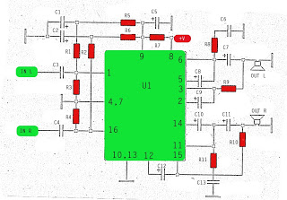
For power supply, a standard 9V battery or a suitable 9V power adapter can be utilized, providing adequate voltage levels for the LM386 and ensuring reliable operation of the circuit. Proper layout and wiring of the components are essential for minimizing interference and ensuring stable performance. Overall, this intercom circuit exemplifies a straightforward yet effective design for basic audio communication needs.The circuit mentioned here is a small easy to build Intercom circuit using one LM386 IC one 2N3904 transistor and few other components. LM386 is a very famous amplifier ICs mostly used by electronics hobbyists in audio circuits. In this circuit the 8 ohms speakers are used for both purposes one as speaker and second as microphone.
The 10K variabl e resistor is used to adjust the volume and 5K variable resistor between the pin 1 and 8 is used to adjust the gain. For switch use DPDT push switches on the both sides. Also include the power on off connection with in the DPDT push switch it will save the battery connected to the circuit all the time and the battery will only connect to the circuit when some one push the switch for talking.
Use 9V battery or 9V power supply with the circuit. 🔗 External reference
Related Circuits
The amplifier circuit utilizes the STK integrated circuit, similar to a previous design. This circuit features two inputs and two outputs, commonly known as a stereo amplifier. It is a power amplifier rated at 2 x 18 Watts with...
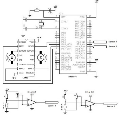
The electronic schematic of the Light Detector Robot can be divided into three main components: the sensor, the microcontroller, and the DC motor driver. The light sensor utilized in this design is a Light Dependent Resistor (LDR), which alters...
A small servo tester for modeling can be very useful in various situations for those who frequently work with servos. The primary function of a servo tester is to produce a pulsing signal with a positive pulse width that...
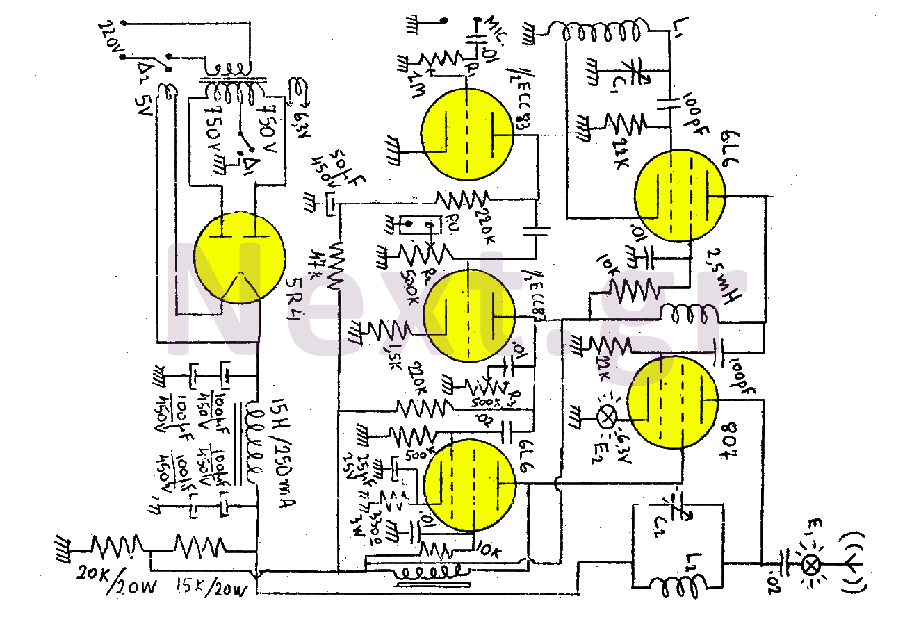
This transmitter consists of a total of five bulbs. The 6L6 tube functions as an oscillator, directing oscillations to the grid of the 807 tube, which serves as the final amplifier and the transmitter output lamp. The amplifier includes...
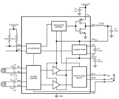
The LM48824's Stereo Headphone Amplifier, utilizing Class G architecture, enhances audio playback time for devices such as MP3 players and mobile TVs. Its adaptive power supply design allows for very low supply rails, effectively doubling power efficiency in comparison...
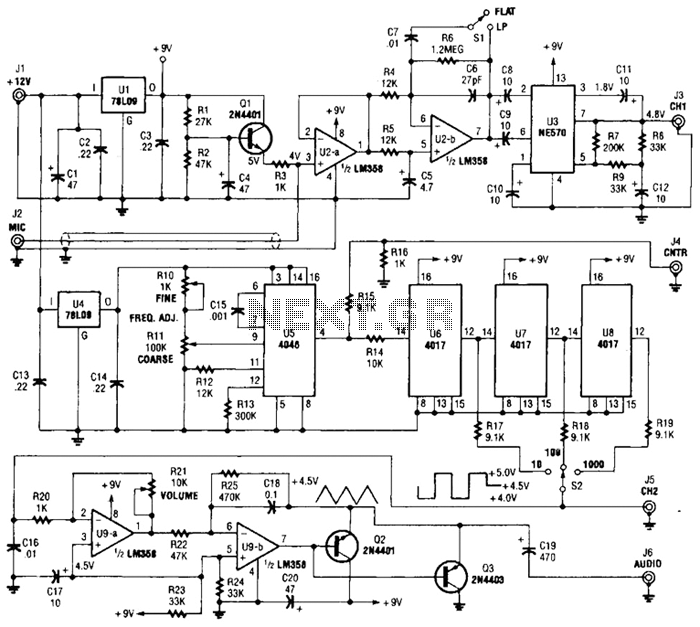
One section of the precision audio frequency generator utilizes an electret microphone element to capture audio from the piano. The captured signal is processed and transmitted to one channel of a dual-trace oscilloscope. The other section of the circuit...