
50W AM Valve RF Transmitter circuit

The radio frequency choke at the 6L6 has an inductance of 2.5 mH for a current of 60 mA. The variable capacitor C2 is also rated at 1000pF but features thinner plates than C1 to prevent arcing between the capacitor plates during operation. Both reinforcements of C2 must be insulated from the chassis due to the high voltage present. The coil L2 consists of 50 turns with a diameter of 4 cm and a wire thickness of 1 mm, with each turn closely wound next to the other. The low-frequency amplifier modulates the carrier wave from the protective grid of the 807 tube, achieving a modulation depth of 90-100%.
The low-frequency amplifier receives input from a crystal microphone, and potentiometer R1 is utilized to control the sound volume. Potentiometer R3, along with a capacitor in series, forms the tone tuning circuit. The primary impedance of the transformer is 5Ω, rated for 70 mA, while the secondary remains inactive during transmitter operation or can be used to control the amplifier's output to a loudspeaker.
The power adapter for the transmitter has a primary voltage of 220V and a secondary output of 2 x 750V at 250 mA, along with 6.3V and 5V outputs. A choke filter rated at 15H for 250 mA is employed, with a voltage divider at the filter's ends consisting of two 15 kΩ resistors rated for 20W each. The switches Δ1 and Δ2 are single-pole, single-throw types. Switch D1 is designed to cut off the high voltage while allowing the filament to operate, enabling the user to listen to other transmitters.
The operational procedure of the transmitter is as follows: with switches Δ1 and Δ2 closed, the user adjusts C1 until the characteristic oscillation sound is heard at the desired frequency. Next, C2 is adjusted until the indicator light E2, aligned with the antenna, flashes at maximum intensity, indicating peak radiating power. With an appropriate antenna, the transmitter can achieve a significant range and satisfactory performance. Indicator lights E1 and E2 operate at 6.3V, and all resistors are rated at 1W unless specified otherwise in the schematic.This transmitter consists of 5 in total bulbs. 6L6 works as an oscillator. Subsequently the oscillation is guided to the guide grid of 807 which acts as the ultimate amplifier and is the transmitter output lamp. The amplifier consists of the ECC83 double-stage as pre-amplifier and 6L6. The power supply feeds both the transmitter and the modulator. 5R4 is used as a rectifier lamp. The coil L1 has been requested by the market as a coil of 6SA7 or 12SA7. The middle reception of the coil is associated with the 6L6 cathode. One end of the coil (closest to the middle reception) is grounded and the other one is connected to one arm of the variable capacitor C1.
The variable capacitor C1 is 1000pF (parallel to the two coaxial) so that the oscillator (600-1800 KC) is tuned in the entire mid wave range.
The radio frequency chuck at the 6L6 rise is 2.5mH for 60mA. Variable capacitor C2 is also 1000pF with somewhat thiner sheets than C1 so that no sparks are generated between the capacitor sheets during the transmitter operation.
As shown in the drawing, both C2 reinforcements have a high voltage so it must be insulated from the chassis. The coil L2 consists of 50 coils. The diameter of the coil is 4cm and the wire thickness is 1mm. One coil is next to each other. The low frequency amplifier modulates the carrier wave from the 807 protective grid. Thus, a 90-100% configuration is achieved.
The low frequency amplifier of the transmitter receives a crystalline microphone.
The potentiometer R1 is used to adjust the volume of the sound. The potentiometer R3 together with the capacitor, which is in series with it, is the tone tuning system. The transformer is 5Ω (primary impedance) for 70mA. The secondary transformer stays dead while the transmitter is operating or we use it to control the amplifier sound with the loudspeaker.
Transmitter power adapter has primary 220V and secondary 2 x 750V for 250mA, 6,3V and 5V.
The choke filter choke is 15H for 250mA. At the ends of the filter is a voltage divider consisting of two resistors of 15KΩ for 20W each. The switches Δ1 and Δ2 are single-pole single-acting. D2 is not located along with the R1 potentiometer. Switch D1 serves to turn off the high voltage by letting the yarn work, so we can listen to other transmitters.
The function of the transmitter is as follows: With switches Δ1 and Δ2 closed, we change C1 until we hear the characteristic blowing of the oscillation at the desired frequency.
Next, set C2 until the indicator light E2, which is in line with the antenna, flashes to the maximum. At this point we have the maximum radiating power of the transmitter. With a good antenna the range of this transmitter is great and the performance is very satisfactory. The indicator lights E1 and E2 are for 6.3V. Also all resistors are 1W unless otherwise noted in the drawing.
Related Circuits
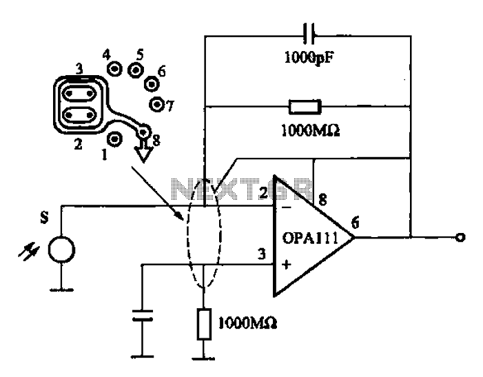
Infrared heat is emitted by an object during non-contact temperature measurement. The measured signal is weak, necessitating the use of highly sensitive thermal infrared sensors with minimal noise. Consequently, the amplifier circuit must also meet stringent requirements, as standard...
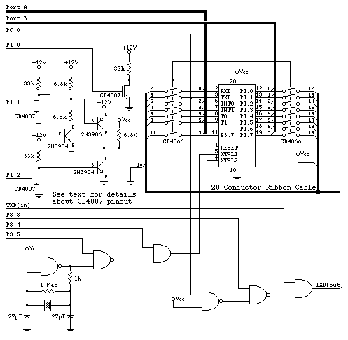
This is a beta release schematic. Use at your own risk. The idea is to add this circuitry to a board that already has RAM at address 2000 and an 82C55 I/O chip to provide ports A, B, and...
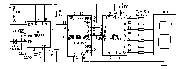
Digital timers feature a clear and precise display. They represent time intervals based on pulse signals, which are decoded by a digital device with a digital display unit. The circuit described pertains to a digital display for these timers,...
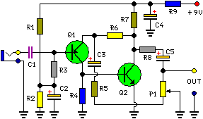
This circuit is primarily designed to provide a microphone input for standard home stereo amplifiers. Utilizing a battery supply effectively eliminates the risk of low-frequency hum interference from mains power, simplifying the connection to the amplifier by removing the...
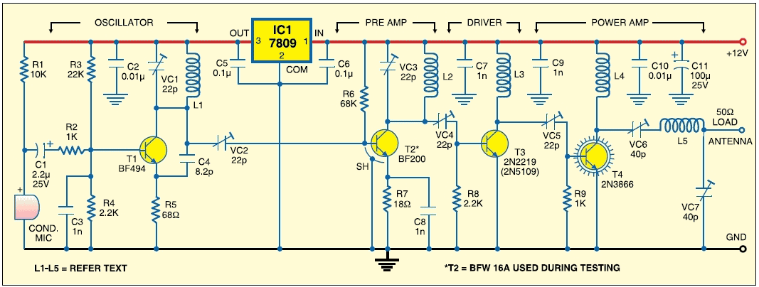
This is a highly stable, harmonic-free, long-range FM transmitter circuit designed for FM frequencies between 88 and 108 MHz. It is capable of covering a range of up to 5 km. The FM transmitter circuit operates within the designated frequency...
This circuit is designed to prevent further damage to old equipment that may be in unknown condition, particularly to devices that are already shorted. The circuit functions as a protective measure for vintage or malfunctioning electronic devices. It is particularly...