
Intercom Circuit Using LM390

The intercom circuit utilizes the LM390 integrated circuit, which is specifically designed for low-power audio applications. The primary function of the LM390 in this circuit is to amplify the audio signals for clear communication between two parties. The circuit is typically powered by a low-voltage DC supply, ensuring safety and efficiency.
In the schematic, the input audio signals are fed into the circuit through a microphone, which converts sound waves into electrical signals. These signals are then processed by the LM390, where the gain can be adjusted using an external component connected to pin 6. The choice of a resistor or a Field Effect Transistor (FET) for gain control allows for flexibility in tuning the audio output to the desired level.
The output of the LM390 is connected to a speaker or earphone, enabling the user to hear the amplified audio signal. Additional passive components, such as capacitors and resistors, are used in the circuit to filter noise and stabilize the power supply, enhancing overall performance and reliability.
This intercom system is suitable for applications where secure and private communication is necessary, such as in residential buildings, offices, or small facilities. Its simplicity and effectiveness make it a popular choice for users seeking a straightforward audio communication solution.This is a circuit for an intercom is a is a stand-alone electronic communications system intended for limited or private dialogue. Below schematic shows the application circuit of LM390 on intercom. Gain control can be done by capacitively coupling a resistor (or FET) from pin 6 to ground. This is the figure of the circuit; 🔗 External reference
Related Circuits
This design outlines a power supply circuit capable of producing a 5V source voltage. The circuit is constructed using TTL integrated circuits (ICs) and features a simple design. In circuits utilizing TTL ICs, the supply voltage is critical, as...
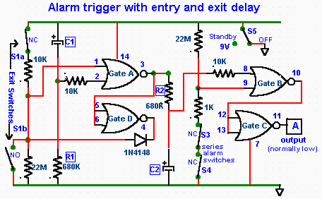
The CD4001 quad 2-input NOR gate is a highly versatile integrated circuit (IC) that can be utilized in numerous applications. This example demonstrates its use in a simple alarm system. The recommended power supply voltage for the CD4001 ranges...
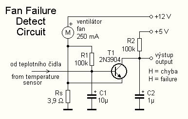
The cooling is not only a PC using a small fan with an electronic commutator. A special feature of these fans is that their removal is less dependent on the load. Indicators monitoring the DC component of current may...
To control the motor, an H-bridge will be utilized in conjunction with a double-pole double-throw (DPDT) relay, as illustrated in the schematic below. For further details, additional resources are available. The proposed circuit employs an H-bridge configuration to facilitate bidirectional...
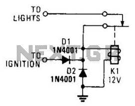
A relay and two diodes are all that is needed; the relay performs the job of a buzzer, so no annunciator is required. When the lights are left on while the ignition is off, the normally closed relay contacts...
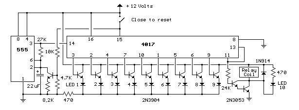
This circuit provides a visual 9-second delay using 10 LEDs before closing a 12-volt relay. When the switch is closed, the 4017 decade counter will reset to zero, illuminating the LED connected to pin 3. The output at pin...