
Interface a uC to PC RS232 with MAX232A

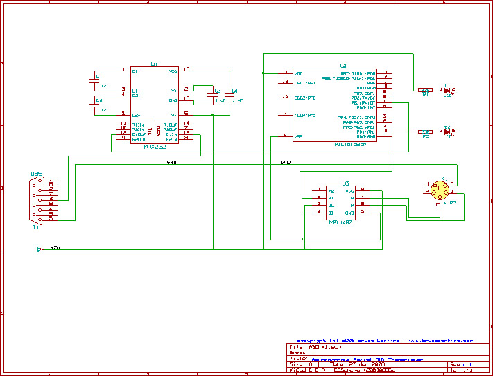
The circuit for interfacing an 8051 microcontroller with a PC via RS232 using the MAX232A is designed to facilitate serial communication. The MAX232A is an integrated circuit that converts TTL (Transistor-Transistor Logic) level signals from the microcontroller to RS232 levels, which are necessary for communication with a PC. The circuit typically includes capacitors connected to the MAX232A to ensure proper voltage conversion and stability.
The 8051 microcontroller features a built-in UART, which allows for asynchronous serial communication. The TXD (transmit data) pin of the microcontroller is connected to the T1OUT pin of the MAX232A, while the RXD (receive data) pin of the microcontroller connects to the R1IN pin of the MAX232A. The MAX232A then interfaces with the PC’s serial port, ensuring that data is transmitted and received correctly.
In addition to the MAX232A, the circuit may include additional components such as resistors and capacitors to filter noise and stabilize the power supply. The power supply for the MAX232A typically requires dual voltages, often +5V and -5V, which can be generated using the capacitors and charge pump circuitry integrated within the MAX232A.
This configuration enables the microcontroller to communicate effectively with the PC, allowing for data transfer and command execution. The use of CMOS technology in the 80C31 variant of the 8051 further enhances its efficiency and applicability in low-power environments, making it suitable for a range of embedded applications. The evolution from UV EPROM to FLASH memory has also significantly improved the flexibility of firmware updates, allowing devices to adapt to new requirements without the need for physical hardware changes.This is the standard configuration on how to Interface a uC like 8051 to PC RS232 with MAX232A. The UART or Serial port was not present in 8049/8749 chips which were the ancestors of 8051/8031. Pages of code were needed to make a software UART in MCS-48. The 8051 integrated the hardware UART and short commands made it tick. The most important inno vation which made uC popular was the C in 80C31. C is for CMOS. This made the chip work cooler and work on even batteries and small power supplies. The 8749 and 8751 are the UV EPROM type of uC. With limited erase/write cycles. The FLASH revolution changed every thing, you could update firmware over a phone line modem. Even without Ethernet, the firmware could be updated by making every embedded device a node on the EPABX. Now TCP/IP and Wi-Fi makes it all very easy. 🔗 External reference
Related Circuits
A GPS modem is a device that receives signals from satellites and provides information about latitude, longitude, altitude, and time. GPS navigators are commonly used in mobile devices to track road maps. The GPS modem includes an antenna that...
U7 is a 6510 microprocessor. One of the features of the 6510 is a built-in parallel I/O port (P0-P5). Pins P3 to P5 control most of the cassette interface circuitry. The P3 pin of U7 outputs the write data...
I designed a simple sinewave generator based on a Analog Devices AD9832 chip. It will generate a sinewave from 0.005 to 12 MHz in 0.005 Hz steps. That's pretty good, and definitely good enough for me! But while waiting...

The interface circuit is placed between the computer's standard video signal output terminal and the television. It amplifies the standard 1V (Peak-to-Peak) video signal to 3V (Peak-to-Peak). The negative feedback circuit consists of transistors T1 and T2, providing a...
The project concept originated nearly two years ago during research for a new lighting board for a small theater. The existing board was nearly twenty years old and in dire need of replacement. However, the costs associated with purchasing...
This RS232 power supply circuit diagram is a simple RS-232 line driver power supply that operates from an input voltage as low as 4.2V and delivers an output of ±12V at ±40 mA with an efficiency of better than...