
RS232 power supply circuit diagram electronic project design

The RS232 power supply circuit is designed to efficiently convert a low input voltage into a dual output voltage of ±12V, suitable for RS-232 line drivers. The LM1578A switching regulator serves as the core component, facilitating the conversion and regulation of voltage. The circuit demonstrates an efficiency exceeding 70%, which is critical for minimizing power loss and heat generation, especially in compact applications.
Load regulation is maintained at ±1.25% across a load range of 10% to 100%, indicating that the output voltage remains stable under varying load conditions. Line regulation further ensures that fluctuations in input voltage do not significantly impact the output, with a specification of ±0.08%. The cycle-by-cycle current limit feature enhances the circuit's reliability by preventing excessive current that could damage components.
The transformer, Pulse Engineering PE-64287, features a turns ratio of 1:1.6:1.6, which is essential for stepping up the voltage to the desired levels. The primary inductance of 50 is critical for ensuring proper operation and efficiency of the transformer in the switching regulator circuit.
The list of components includes resistors R1 (10 kΩ), R2 (240 kΩ), and R3 (240 kΩ), which are used for setting the feedback and control parameters of the regulator. R4 (0.1Ω) serves as a current sensing resistor. Capacitors C1 (1000 pF) and C2 (18 pF) are used for filtering and stability, while C3 (220 µF), C4 (220 µF), and C5 (100 µF) provide bulk energy storage to smooth out the output voltage. C6 (0.1 µF) is included for high-frequency decoupling. The diodes, specifically the 1N5819 type, are used for rectification and provide a robust path for current flow while preventing reverse polarity.
Overall, this RS232 power supply circuit is an effective solution for applications requiring reliable ±12V power for RS-232 line drivers, with careful consideration given to efficiency, regulation, and component selection.This RS232 power supply circuit diagram is an simple RS-232 Line Driver Power Supply, that operates from an input voltage as low as 4. 2V, and delivers an output of ±12V at ±40 mA with an efficiency of better than 70%. This RS232 power supply circuit provides a load regulation of ±1. 25% (from 10% to 100% of full load) and a line regulation of ± 0. 08%. Other notable features include a cycle-by-cycle current limit and an output voltage ripple of less than 40 mVp-p. This power supply circuit is based on the LM1578A switching regulator designed by National Semiconductor and can be used to convert the already existing supply into a separate ±12V supply for powering the interface line drivers.
The transformer used in the power supply was a Pulse Engineering PE-64287 with turns ratio of Np:Ns:Ns = 1:1. 6:1. 6 and primary inductance of 50. Values for components are : R1 = 10 k ©, R2 = 240 k ©, R3 = 240 k ©, R4 = 0. 1 ©, C1 = 1000 pF, C2 = 18 pF, C3 = 220 F, C4 = 220 F, C5 = 100 F, C6 = 0. 1 F and all diodes are 1N5819 type. 🔗 External reference
Related Circuits
Desulfation is the process of reversing sulfation that occurs in a lead-acid battery over time. Desulfation partially restores the battery's ability to hold a charge, which is diminished due to sulfation. Desulfation is a critical maintenance procedure for lead-acid batteries,...

The ADC574A is a 12-bit successive approximation analog-to-digital converter (ADC). The request is for information on how this integrated circuit (IC) operates. The ADC574A operates by converting an analog input signal into a digital output signal using the successive approximation...
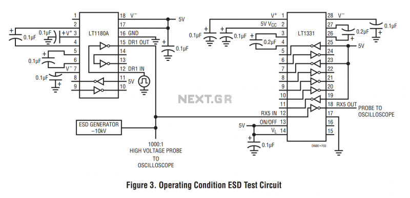
The machine model, commonly used for ESD testing in Japan, is a more severe ESD test. This model simulates metallic contact between the device under test and a charged body. The source capacitor is 200pF with no limiting resistor....
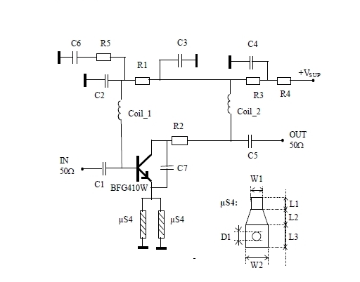
This 900 MHz amplifier circuit is constructed using the BFG480W transistor, which exhibits excellent linearity performance. As a result, the BFG480W is highly suitable for low-noise amplifiers (LNAs) that require high linearity. The 900 MHz amplifier circuit utilizing the BFG480W...
This TDA2030 35-watt audio amplifier circuit project is designed to deliver an output power of 35 watts into an 8-ohm load. The TDA2030 is a monolithic integrated circuit housed in a Pentawatt package, intended for use as a low-frequency...
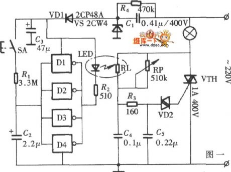
The diagram illustrates a lamp dimmer that gradually increases and decreases light intensity. This feature prevents sudden illumination, which can be a shock to the human eye, and also minimizes damage caused by inrush current when the lamp is...