
interfacing of lcd with at89s528051

The interfacing of a 16x2 LCD with the AT89S52 microcontroller involves connecting several pins from the LCD to the microcontroller. The LCD typically has 16 pins, out of which 8 are data pins (D0 to D7), 3 control pins (RS, RW, and E), and 5 power and ground connections.
1. **Pin Configuration**: The LCD's pins are connected as follows:
- **Data Pins (D0-D7)**: These pins are connected to the microcontroller's Port 1 (P1.0 to P1.7). Only 4 data pins (D4-D7) may be used for 4-bit mode operation, which reduces the number of connections required.
- **Register Select (RS)**: This pin determines whether the data being sent to the LCD is command or character data. It is connected to a general-purpose I/O pin on the microcontroller.
- **Read/Write (RW)**: This pin is used to select the operation mode (read or write). It is typically grounded for write operations.
- **Enable (E)**: This pin is used to latch the data present on the data pins. It is connected to another I/O pin on the microcontroller.
2. **Power Supply**: The LCD requires a power supply of 5V. The VSS pin connects to ground, while the VDD pin connects to the positive supply voltage. The contrast of the display can be adjusted using a potentiometer connected to the V0 pin.
3. **Initialization**: The microcontroller must initialize the LCD by sending a series of commands to set it up for operation. This includes setting the data length (4-bit or 8-bit), number of display lines, and character font.
4. **Data Display**: Once initialized, the microcontroller can send data to be displayed on the LCD. This is done by writing to the data pins and toggling the enable pin to signal the LCD to read the data.
5. **Programming**: The microcontroller code will include functions to send commands and data to the LCD, as well as functions to initialize the display and control the cursor.
This setup allows for a versatile interface for displaying information in various applications, such as user interfaces for embedded systems, where visual output is essential for user interaction.This tutorial explains one of the real world application of 8051. Here we are going to explain how a 16x2 LCD is interfaced with AT89S52. 1) LCD: 16x2 LCD is used as output by the controller to show any data or any information to user .The name 16x2 LCD means 16 number of data can be can be written on.. 🔗 External reference
Related Circuits
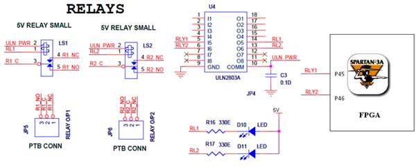
The Spartan-3an board features external 5V relay interfacing, as illustrated in the accompanying figure. The ULN2803 acts as a driver for the FPGA I/O lines, with the driver's outputs connected to the relay modules. A PTB connector is available...
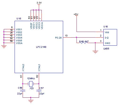
The LM35 series consists of precision integrated-circuit temperature sensors, with an output voltage that is linearly proportional to the temperature in degrees Celsius. The sensor's output can be converted to a digital signal, facilitating easy connection to a microcontroller....
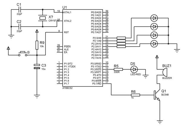
How to interface a +5V buzzer with the IC 89S52. It has been suggested to use two BC547 NPN transistors for this purpose. To interface a +5V buzzer with the 89S52 microcontroller, a common approach involves using transistors to...
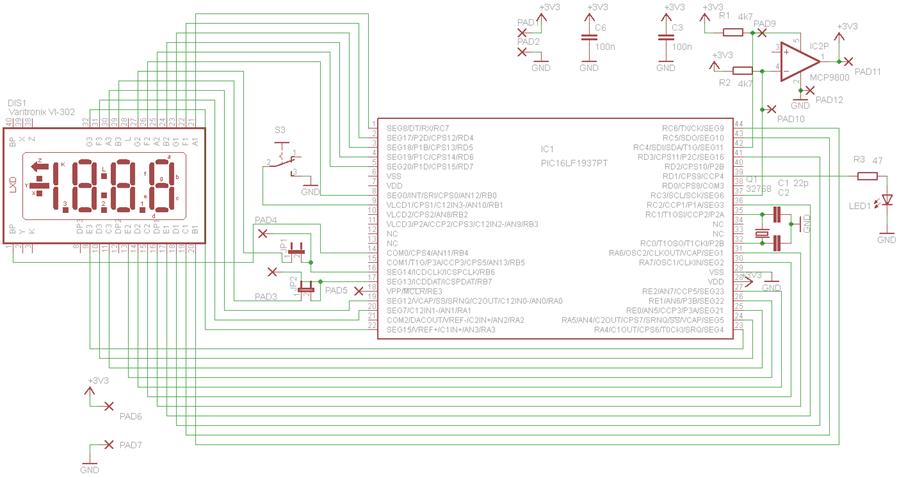
This circuit is centered around the PIC16LF1937 microcontroller, which is essentially a compact computer integrated into a single chip, encompassing RAM, EEPROM, I/O ports, and a CPU. When purchased, the chip is unprogrammed, necessitating the compilation of source code...
In many projects, alphanumeric LCDs are utilized, which are internally driven by Hitachi's industry-standard HD44780 controller. These displays can be driven... Alphanumeric LCDs that utilize the HD44780 controller are widely used in various electronic projects due to their reliability and...
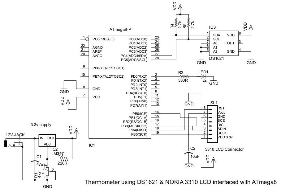
This document presents an application utilizing the Nokia 3310 LCD for designing a thermometer using the DS1621 temperature sensor IC. The DS1621 is an 8-pin sensor manufactured by Maxim. The circuit design involves integrating the DS1621 temperature sensor with a...