
interfacing buzzer with 8952

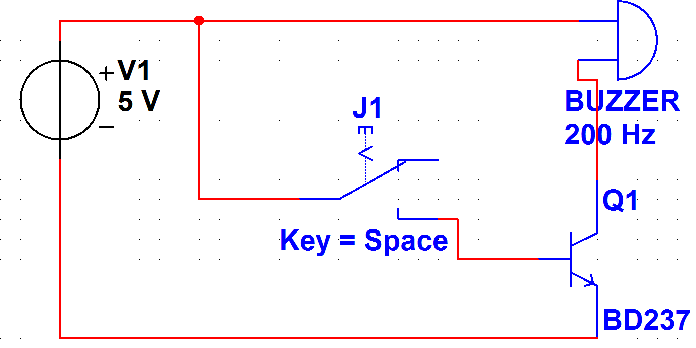
To interface a +5V buzzer with the 89S52 microcontroller, a common approach involves using transistors to control the buzzer's operation. The BC547 NPN transistor is suitable for this application due to its ability to handle low current and voltage levels effectively.
The circuit will typically consist of two BC547 transistors arranged in a configuration that allows for the control of the buzzer. The first transistor can be used to switch the buzzer on and off based on a control signal from the 89S52 microcontroller. The second transistor may serve as a buffer or amplifier, ensuring that the control signal is sufficient to drive the buzzer.
In the schematic, the base of the first BC547 transistor is connected to a digital output pin of the 89S52 microcontroller through a current-limiting resistor. This resistor is crucial to prevent excessive current from flowing into the base, which could damage the microcontroller. The collector of the first transistor is connected to one terminal of the buzzer, while the emitter is grounded.
The second BC547 transistor can be connected in a similar manner, where its base is driven by the output of the first transistor. The collector of the second transistor is connected to the other terminal of the buzzer, and its emitter is also grounded. This arrangement allows for a more robust control of the buzzer, enabling it to operate effectively with the 89S52.
Power for the buzzer is supplied from a +5V source, which is connected to the buzzer's terminal that is not connected to the transistors. When the microcontroller sends a high signal to the base of the first transistor, it turns on, allowing current to flow through the buzzer and activating it. The second transistor further ensures that the buzzer receives adequate current, enhancing its performance.
Overall, this circuit design provides a reliable method for interfacing a +5V buzzer with the 89S52 microcontroller, utilizing the BC547 NPN transistors to control the buzzer's operation efficiently.hey! how to interface a +5V buzzer with IC 89S52. someone suggested me to use two bc547 npn transistor. this is its schematic. buzzer interface.png i.. 🔗 External reference
Related Circuits
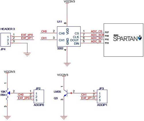
The Spartan-6 board features a 2-channel, 12-bit SPI ADC, as shown in the accompanying figure. In synchronous serial communication, a clock line (SCK in the case of SPI) is used to synchronize data transfer, with the clock being controlled...
The PSoC 3 Primer Kit is specifically designed to assist students in mastering the necessary skills in embedded systems. The kit is structured to enable easy utilization of all possible features of the microcontroller. It supports the FX2LP Programmer,...
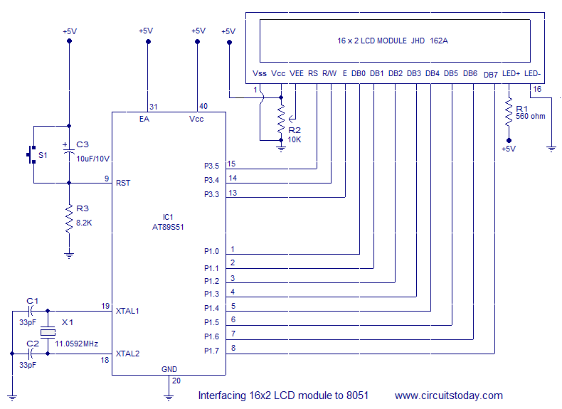
Interfacing a 16x2 alphanumeric LCD module with the AT89S51 microcontroller. The circuit diagram, theory, and program are included. JHD162 LCD module pinout and commands are provided. The integration of a 16x2 alphanumeric LCD module with the AT89S51 microcontroller involves several...
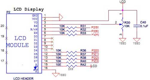
The LCD does not effectively assist in programming due to the absence of a debugging program. It is necessary to display the results of calculations, the contents of variables, or other debugging information on the LCD to understand the...
A PB-12N23PW-05Q buzzer is being used with an ATmega 162 microcontroller. Direct connection to the microcontroller pin is not feasible due to the maximum sourcing capability of 20 mA as stated in the ATmega 162 datasheet, while the buzzer...
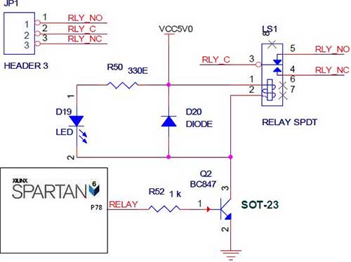
The Spartan-6 board features onboard 5V relay interfacing, as illustrated in the accompanying figure. The ULN2803 serves as a driver for the FPGA I/O lines, with the driver's outputs connected to the relay modules. A PTB connector is provided...