
Interfacing the LCD module to PC parallel port

The interfacing of a 20x4 LCD module with a PC parallel port involves several steps, which include hardware connections, software setup, and programming. The 20x4 LCD module is capable of displaying 20 characters per line and has four lines, making it suitable for various applications where readable output is required.
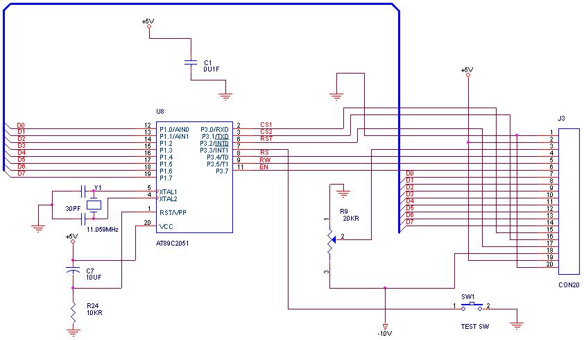
To begin, the hardware setup necessitates connecting the LCD module to the parallel port of the PC. The parallel port typically consists of 25 pins, with specific pins designated for data transmission, control signals, and ground connections. The data pins (usually pins 2 to 9) of the parallel port are connected to the data pins of the LCD module. Additionally, control pins such as the Register Select (RS), Read/Write (R/W), and Enable (E) pins of the LCD must be connected to the appropriate pins on the parallel port.
A common approach involves using a resistor network or buffer to ensure that the signal levels from the parallel port are compatible with the LCD module's input requirements. It is also essential to connect the power supply pins of the LCD module to a suitable voltage source, typically +5V.
Once the hardware connections are established, software configuration must be addressed. The programming can be accomplished using languages such as C or Python, which can directly access the parallel port. Libraries or functions specific to the chosen programming language may be required to facilitate communication with the parallel port. The software should initialize the LCD, set the mode of operation (e.g., 4-bit or 8-bit), and send commands and data to display characters.
The process involves sending commands to configure the display settings, such as clearing the screen, setting the cursor position, and writing characters to the display. Proper timing between commands and data transmission is crucial to ensure reliable operation.
In conclusion, interfacing a 20x4 LCD module to a PC parallel port encompasses careful hardware connections, appropriate software programming, and adherence to timing requirements for successful communication. This setup allows for effective display output for various applications, enhancing user interaction with the system.Tutorial on Interfacing the 20x4 LCD module to PC parallel port. 🔗 External reference
Related Circuits
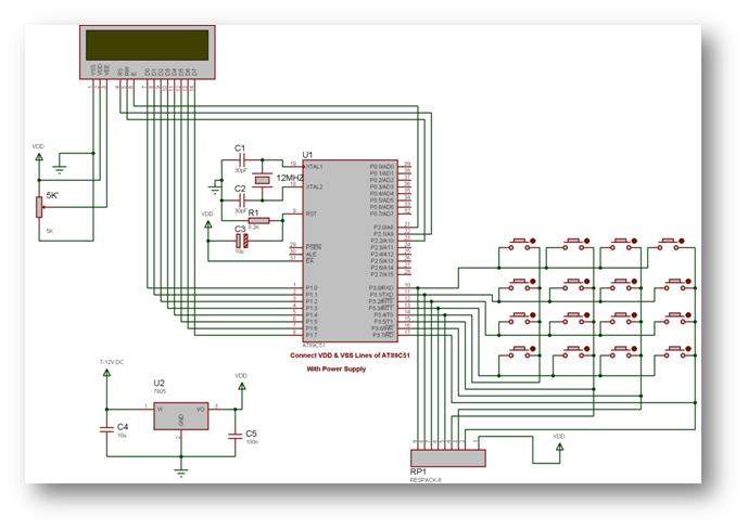
When using an LCD in 4-bit mode, data must be sent twice, whereas in 8-bit mode, it is sent only once. This increases the workload on the microcontroller when interfacing with the LCD. If the microcontroller is handling only...
Microcontrollers are merely silicon wafers until programmed to perform specific tasks based on user requirements. Microcontrollers serve as the fundamental building blocks in modern electronic systems, acting as the brains that control various functions within devices. They consist of a...
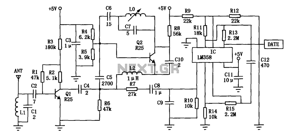
The DF data transmission module operates at a frequency of 315 MHz and utilizes a surface acoustic wave (SAW) resonator for frequency stabilization, ensuring high frequency stability. The frequency drift remains minimal, at only 3 x 10^-6, across a...
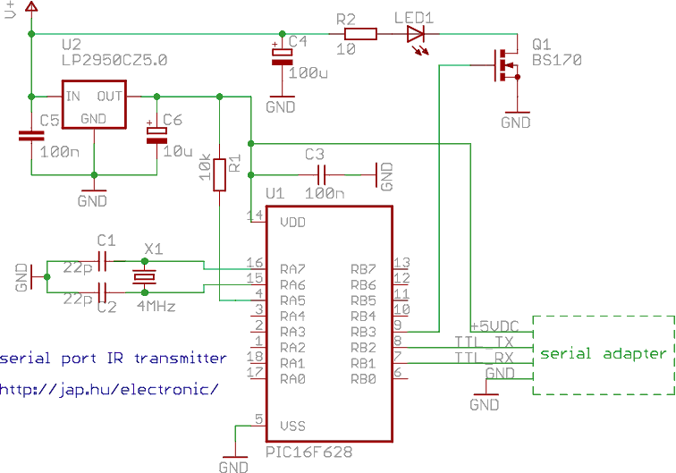
This is a programmable infrared (remote control) transmitter, which can be controlled from a PC serial port. It is capable of sending many remote control formats, including the Philips RC-5 standard. Exact formats with the timing parameter names are...

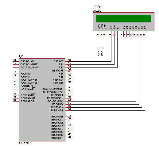
The schematic for this tutorial is illustrated below and includes all necessary components for the tutorial to function. The PIC programming circuitry is not included, as it is assumed that the PIC is either programmed externally or that the...
How can graphical LCDs be controlled using a microcontroller? Is there any datasheet available? Graphical LCDs (Liquid Crystal Displays) are widely used in various electronic applications for displaying complex graphics and text. To control these displays with a microcontroller, several...