
16x2 LCD Display Custom Characters Circuit

The schematic presented includes a comprehensive layout essential for interfacing a PIC microcontroller with a 16x2 LCD. The microcontroller's PORTD is designated for the data pins of the LCD, facilitating a direct connection to the eight data lines (DB0 to DB7) required for data transmission. This arrangement allows for efficient communication between the PIC and the LCD, as the data pins are aligned with the corresponding pin numbers on the microcontroller.
Control signals are managed through PORTB, with the lower three bits designated for the control pins of the LCD. The RS (Register Select) pin determines whether the data being sent is command or character data, while the R/W (Read/Write) pin allows for reading from or writing to the LCD. The E (Enable) pin is essential for signaling the LCD to process the data present on the data lines.
The inclusion of a 5k trimpot in the schematic is crucial for adjusting the contrast of the LCD display. Properly connecting the trimpot between the power supply and ground allows users to fine-tune the visibility of the displayed characters. This adjustment is vital for optimal readability in various lighting conditions.
For the backlight functionality, pins 15 and 16 of the LCD are utilized. A resistor is placed in series with the anode of the LED backlight, while the cathode is connected to ground. This simple circuit design ensures that the backlight is activated when the circuit is powered, enhancing the display's visibility in low-light environments.
Overall, the schematic provides a clear and effective guide for wiring the necessary components to successfully implement the tutorial, ensuring a functional and user-friendly interface with the 16x2 LCD.The schematic for this tutorial can be seen drawn out below. It includes everything you`d need to wire up for the tutorial to work. PIC programming circuitry is not included in the schematic as I`m assuming either you`re programming the PIC out of circuit or can add the few elements into the circuit on your own for in-circuit programming. The 16x 2 LCD interface has 8 data bits (DB0~DB7) and 3 control pins (RS, R/W*, E). The data bits are connected to the 8 pins of PORTD on the PIC. A special note to take is that the LCD data pins match the PIC pin-numbers. The control lines are connected to the lower 3 bits of PORTB on the PIC. As mentioned in the parts list, the 5k trimpot will control the contrast for the LCD. The schematic above shows you how the trimpot should be connected to the LCD, Power and Ground. After it is connected when you turn the trimpot dial characters on the screen will appear lighter and darker. Most 16x2 LCD`s have a backlight LED unless you opted to save a few bucks. There`s nothing special about these two pins (15 and 16). Slap a resistor infront of anode and connect the cathode to ground and immediately the backlight should turn on.
🔗 External reference
Related Circuits
This low-noise microphone amplifier is built with the MAT02 produced by PMI. This microphone amplifier is highly efficient and features a very low noise level. The amplification can be set to either 20 dB or 23.5 dB (10x or...
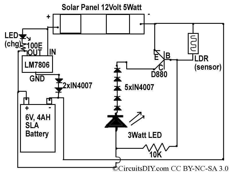
This document discusses a simple solar LED circuit. Solar panels range from 12 volts and 3 watts to larger sizes. To store energy, a 12-volt battery is required. The preferred choice is a sealed lead-acid (SLA) sealed maintenance-free (SMF)...
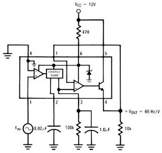
The LM2917 IC chip is specifically designed as a Frequency to Voltage Converter. It requires only a few external components for its operation. The datasheet for the LM2917 IC includes several application examples of the Frequency to Voltage Converter....
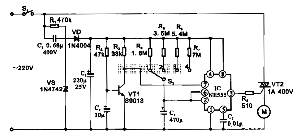
The fan motor driving circuit is depicted as a basic configuration comprising a power circuit and a motor drive circuit. The power supply circuit primarily consists of a power switch (SI), a capacitor (C1), resistors (R1), a Zener diode...
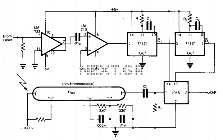
The application involves observing the light pulse emerging from a thick specimen after transillumination by a laser pulse. Pulses derived from the laser source are amplified using a Video Amplifier LM733. The reference level is set to 1 V...
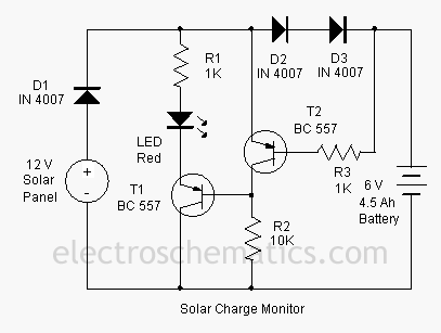
This add-on circuit can be attached to the solar charger to indicate whether the battery is charging. It lights a red LED to signal that the battery is charging. The described add-on circuit serves as a visual indicator for the...