
Inverter Cicuit DIY
The CFL lighting kit from Alfa is designed to accommodate compact fluorescent lamps (CFLs) with power ratings of 9W, 11W, and up to 20W. The circuit is engineered to ensure stable operation, which is critical for maintaining the longevity and performance of the lighting solutions. The inclusion of a power factor of 0.50 indicates that the circuit is optimized for energy efficiency, allowing for effective management of electrical power and reducing wastage.
The circuit typically includes essential components such as a ballast, which regulates the current to the CFL, ensuring that the lamp operates within its specified range. The ballast may be either electromagnetic or electronic, with the latter being more common in modern applications due to its lightweight and compact size, as well as its ability to provide a more stable output.
Additionally, the kit may feature protective elements such as fuses or circuit breakers to prevent damage from overcurrent situations. These components are crucial in safeguarding both the circuit and the connected CFL from potential electrical failures.
The design of the circuit also emphasizes thermal management, ensuring that heat generated during operation is dissipated effectively. This is important for maintaining the performance of the CFL and prolonging its lifespan.
Overall, the Alfa CFL lighting kit is a reliable solution for various lighting applications, providing efficiency, stability, and longevity in its operation.This CFL lighting kit is available from a reputed brand alfa, which is known for it`s circuits in applications of inverter like products. We get a good stable circuit from them. The below kit is for lighting a PL of 9Watt, 11Watt or a CFL of upto 20 watt (of course PF=0. 50 CFL`s). Earlier we Read More †’ 🔗 External reference
Related Circuits
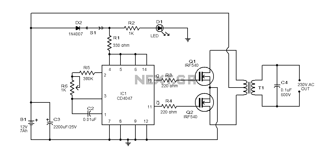
This document provides an explanation of a simple 100-watt inverter circuit using the IC CD4047 and the IRF540 MOSFET. The circuit is designed to be simple, cost-effective, and suitable for assembly on a veroboard. The CD4047 is a low-power...
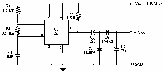
This circuit inverts the polarity of the input. Output is limited to less than 200mA. More: U1 NE555 timer IC R1 1.2k ohm resistor R2 3.9k ohm resistor R3 1k ohm resistor C1 0.05 uF ceramic capacitor C2, C3...
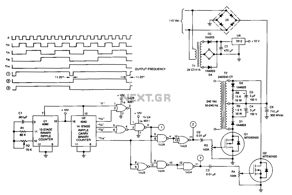
U1 is a 4060 12-stage binary ripple counter that operates as a free-running oscillator, with its frequency of oscillation calculated as 1/2.2 CIR2. The output from U1 is fed into U2, a 14-stage binary ripple counter that generates square-wave...
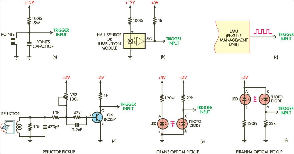
The document provides an extract from another SC article discussing a simple programmable TCI (Transistor Controlled Ignition) that features nearly identical trigger input circuits to the DIY-CDI (Capacitor Discharge Ignition) system. It highlights that the trigger circuits are described...
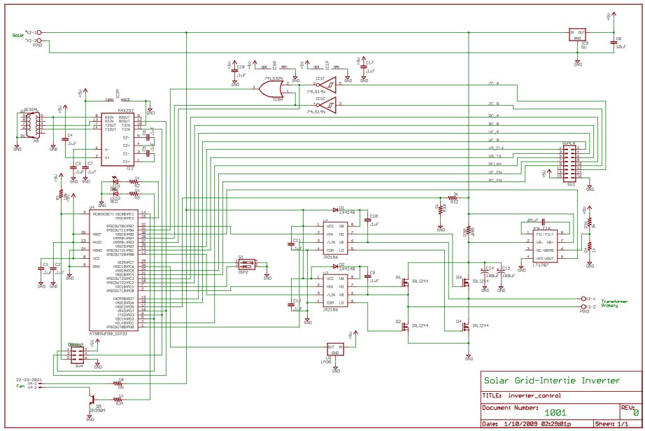
For the last year, a prototype for a solar inverter that can be grid-intertied has been developed. A solar inverter converts 12V DC (or other voltages) from solar panels. The solar inverter is a crucial component in photovoltaic systems, responsible...
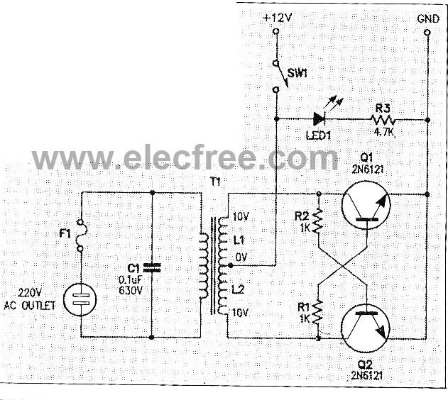
This micro inverter is a small-sized device that modifies energy from a battery, producing an output voltage of approximately 220V AC at 50Hz. The circuit comprises two transistors that function as a pulse oscillator or square wave generator, driving...
Warning: include(partials/cookie-banner.php): Failed to open stream: Permission denied in /var/www/html/nextgr/view-circuit.php on line 713
Warning: include(): Failed opening 'partials/cookie-banner.php' for inclusion (include_path='.:/usr/share/php') in /var/www/html/nextgr/view-circuit.php on line 713