Ion Ray Gun
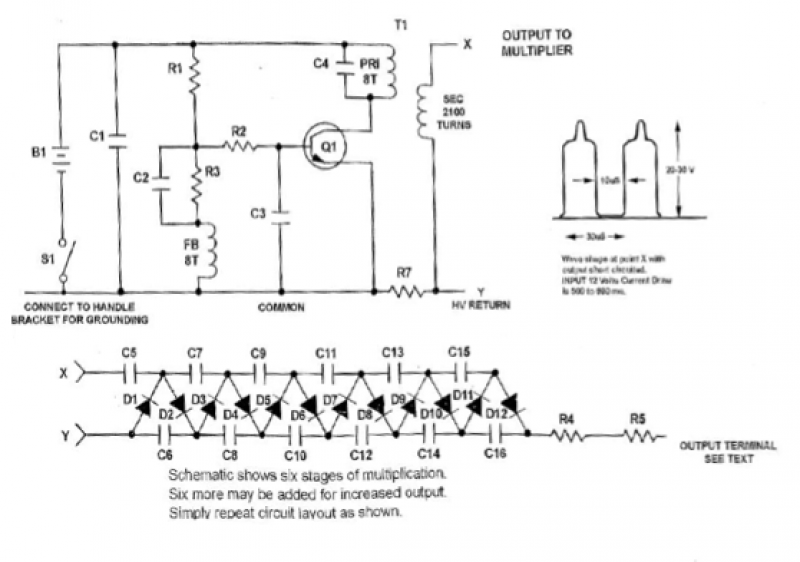
Parts List: R1 2.2K, R2 27Ω, R3 220Ω, R4-R5 100MΩ, C1 0.47µF/50V, C2-C3 0.047µF to 0.068µF, C4 1µF/100V, C5-C16 0.001µF/15KV, D1-D12 22KV 5mA Avalanche Diodes, Q1 MJE3055, TO-220 NPN, T1 2100:8:8, BH1 8 Cell AA Battery Holder, HS1 Heat Sink Bracket. Electrons accumulate at sharp points in metals and are emitted from a sharp needle-like point. A negatively charged plate can be employed as an electron reflector to focus electrons, creating a narrow beam. A more concentrated beam may be achieved with alternative structures, although experimental validation is required. To prevent loss from corona discharge, the entire wire and reflector, except for the sharp emitter, should be insulated with a smooth material such as silicone.
The configuration illustrated can be used to cluster electrons using a magnetic field. If the magnetic field is rapidly deactivated, the clustered electrons are released and can be directed toward a target due to the focusing effect of the negatively charged reflector. A pulsed magnetic field can be generated by a pulsed capacitor discharge. When a high-voltage capacitor discharges through a solenoid via a silicon-controlled rectifier (SCR), a certain quantity of electrons and negative ions are captured and organized by the magnetic field within the solenoid. As the pulse dissipates, they are released and focused by the negatively charged reflector.
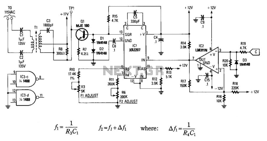
The schematic involves a series of components designed to generate and manipulate high-voltage signals. Resistors R1, R2, and R3 are used to control current flow and voltage levels throughout the circuit, while R4 and R5 provide high resistance to limit leakage currents. Capacitors C1, C2, and C4 serve to store and filter energy, crucial for the timing and stability of the discharge events. The avalanche diodes D1-D12 are critical for protecting the circuit from high-voltage spikes, ensuring the integrity of the system during operation.
The transistor Q1 (MJE3055) functions as a switch or amplifier, allowing for the control of high currents necessary for the discharge process. The transformer (T1) is essential for stepping up the voltage to the required levels for ion generation. The battery holder (BH1) provides the necessary power supply, while the heat sink bracket (HS1) helps manage thermal conditions, ensuring that components do not overheat during operation.
The focusing mechanism described relies heavily on the principles of electrostatics and magnetostatics, where the arrangement of charged elements creates a potential difference that influences the trajectory of emitted electrons. The use of a negatively charged reflector is particularly significant, as it enhances the control over the emitted electron beam, allowing for precise targeting and improved performance in applications such as ion propulsion or material processing. Further experimentation and refinement of this design could lead to advancements in the efficiency and effectiveness of ion generation and launching systems.I found the following schematic from online sources. It’s about generating and launching ions. I did not built this circuit. But I’ll present some ideas on how to focus ions so that they will travel a longer distance.
Parts List R1 2.2K R2 27Ω R3 220Ω R4-R5 100MΩ C1 0.47µF/50V
C2-C3 0.047µF to 0.068µF C4 1µF/100V C5-C16 0.001µF/15KV D1-D12 22KV 5mA Avalanche Diodes Q1 MJE3055, TO-220 NPN T1 2100:8:8 BH1 8 Cell AA Battery Holder HS1 Heat Sink Bracket
Electrons gather at sharp points in metals. Electrons are emitted from a needle like sharp point as shown in Fig. 2. A negatively-charged plate may be used as an electron reflector to focus electrons along a line, thus producing a tight beam as shown in Fig.
1(b). Even a tighter beam is possible if the needle point is replaced with the structure shown in Fig. 1(c), though experimental verification is needed. To avoid loss due to corona, the entire wire and the reflector, except the sharp emitter, should be covered by an isolating material such as silicon etc. and surface variations should be very smooth.
Configuration shown in Fig. 3 can be used to bunch electrons using a magnetic field. Later, if the magnetic field is cut rapidly, bunched electrons are released and due to the focusing effect of the negatively charged reflector (NCR), they can be launched on to a target.
A pulsed magnetic field would do the job if it’s generated by a pulsed capacitor discharge. So, if a HV capacitor is discharged on to a solenoid through an SCR, some amount of electrons and negative ions are captured and bunched by the magnetic field inside the solenoid. As the pulse dies out, they are released and focused by NCR. By 4beowulf7 - [email protected]
