
Commodore 64 I/O ROM Expansion Port

The Programmable Logic Array (PLA) U17 plays a crucial role in the address decoding and selection of various ROMs within the system. The outputs from the PLA are specifically designed to indicate when certain ROMs are active based on the address ranges being accessed by the microprocessor.
When the BASIC ROM is selected, the output at F1 pin 17 transitions to a low state. This indicates that the microprocessor is currently accessing the BASIC ROM, which is mapped to memory locations ranging from $A000 to $BFFF. The KERNAL ROM, which contains essential system routines, is accessed when the F2 pin 16 goes low, indicating that the microprocessor is addressing memory locations from $E000 to $FFFF.
The CHARACTER GENERATOR ROM, responsible for generating the character set displayed on the screen, is selected when the F3 pin 15 goes low. This ROM is mapped to the address range of $D000 to $DFFF.
In addition to ROM selection, the expansion port serves as an interface for additional peripherals and cartridges, extending the microprocessor's address, data, and control bus. The ROML and ROMH outputs from the PLA are critical in decoding the address ranges for the ROMs. ROML is responsible for addresses $8000 to $9FFF, while ROMH handles addresses $E000 to $FFFF, facilitating the selection of cartridges inserted into the expansion port.
Furthermore, I/O operations are managed through the U15 component. The I/O 1 input from U15 decodes addresses within the range of $DE00 to $DEFF, while the I/O 2 output from U15 decodes addresses from $DF00 to $DFFF. This structure allows for effective communication between the microprocessor and various I/O devices, ensuring that the system operates efficiently and effectively. The design and functionality of the PLA and associated components are integral to the overall performance and capability of the electronic system.The output F1 pin 17 of the PLA U17 goes "low" when the BASIC ROM is selected. The KERNAL ROM resides at locations $E000 - $FFFF. The output F2 pin 16 of the PLA U17 goes "low" when the KERNAL ROM is selected. The CHARACTER GENERATOR ROM resides at locations $D000 - $DFFF. The output F3 pin 15 of the P LA U17 goes "low" when the Character Generator ROM is selected. The expansion port is an extension of the microprocessor address, data, and control bus. ROML decodes addresses $8000 - $9FFF, and ROMH decodes addresses $E000 - $FFFF. These are outputs from the PLA used to select the catridge inserted in the expansion port. I/O 1 input from U15 decodes addresses $DE00 - $DEFF. I/O 2 output from U15 decodes addresses $DF00 - $DFFF. 🔗 External reference
Related Circuits
With the rapid development of the social economy, the demand for electric energy continues to increase. In light of the diminishing availability of non-renewable energy sources, such as fossil fuels, many countries are recognizing the importance of energy conservation...
Operational amplifiers (op-amps) are highly versatile components in electronic circuits. However, one significant limitation is their need for a dual power supply, which can restrict their use in applications where a dual supply is impractical or cost-prohibitive. The circuit...
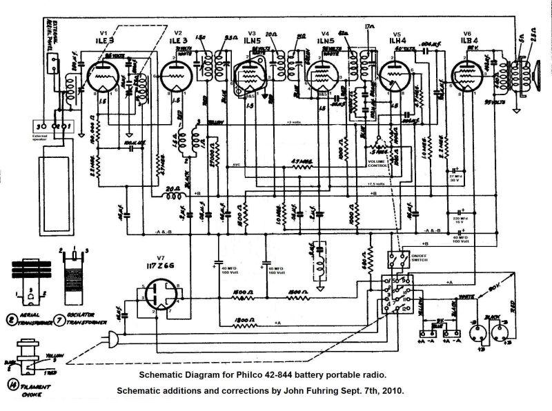
It is a handsome battery-operated portable radio with a roll-top design that remains aesthetically pleasing even today. Initially, the radio was non-functional due to a burned-out detector tube, and the availability of a replacement was uncertain. The radio lacked...
I keep all rights to those circuits myself. You may freely build those circuits to yourself and your friends, but commercial use of those circuits is not allowed. NOTE: Those circuits are old designs from time when I was...
The circuit below illustrates powering a LED (or two) from the 120 volt AC line using a capacitor to drop the voltage and a small resistor to limit the inrush current. Since the capacitor must pass current in both...
A common issue encountered is that individuals possess a schematic, also known as a circuit diagram, that they wish to construct. However, they discover that there are... Building a circuit from a schematic requires a clear understanding of the components...