
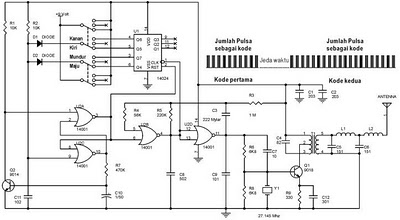
ir detector circuit

The IR detector circuit operates on the principle of phototransistor detection, where Phototransistor T1 is sensitive to infrared wavelengths. When an IR source is directed towards T1, it generates a small current in response to the incoming infrared light. This current is not sufficient to drive an LED directly; hence, the signal is fed into transistor T2, which is configured in a common-emitter amplifier configuration.
Transistor T2 amplifies the small current from T1, resulting in a larger output current capable of driving the LED. The LED is connected in series with a current-limiting resistor to prevent excessive current from damaging the LED. The circuit may also include a power supply, typically a battery, and additional passive components such as capacitors for stability and filtering, as well as potentiometers for adjusting sensitivity.
In practical applications, this IR detector circuit can be used in remote control systems, motion detectors, and other devices that rely on infrared communication. The simplicity of the design allows for easy integration into various projects, providing a visual indicator of infrared activity, which is essential for troubleshooting and verification of IR-emitting devices.Our eyes are very sensitive to light but they cannot see the IR (Infrared) radiations so it is some time difficult to test or check the equipments which emits infrared to confirm that either they are working or not. So here is the IR detector circuit which will detect IR from any equipment which emits IR and lights up an LED which will show the in
dication of IR beam. The heart of the circuit is Phototransistor T1 which will detect the infrared beam. The transistor T2 is working as an amplifier which amplifies the output of T1 and lights the LED which indicates that your equipment is working and emitting infrared beam. 🔗 External reference
Related Circuits

Joule thief circuit along with videos, circuit diagrams, and explanations. The Joule thief circuit is a minimalist boost converter designed to extract energy from low-voltage sources, such as depleted batteries. This circuit is particularly effective for powering small electronic...
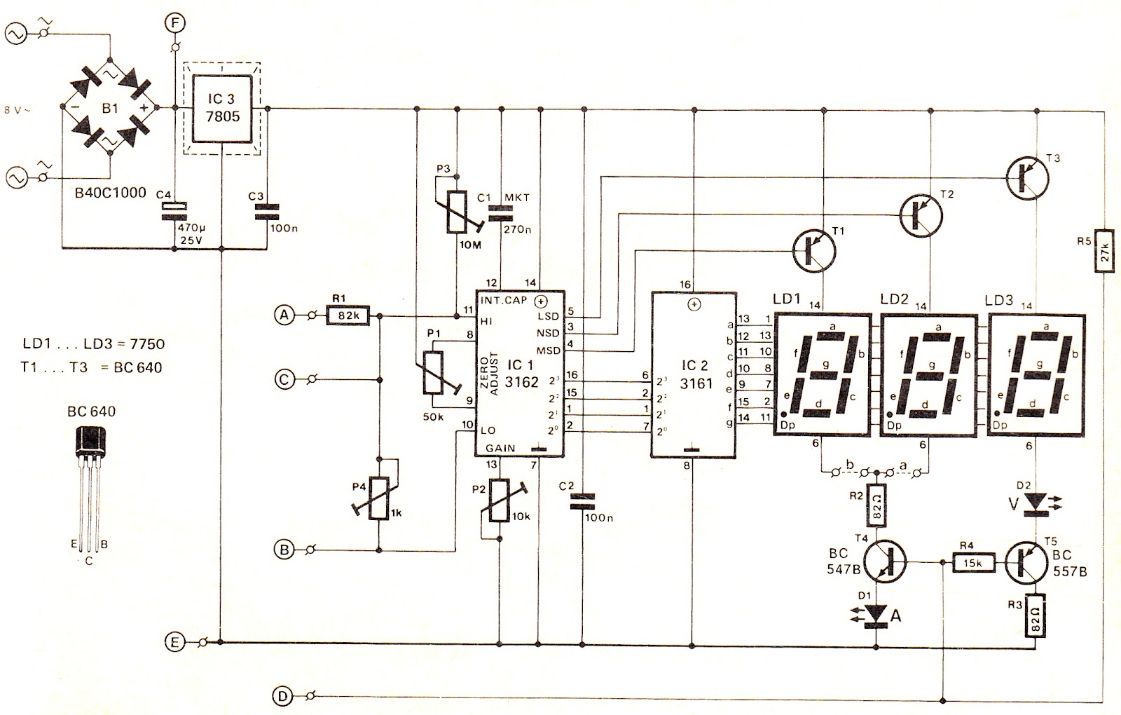
This voltage/current (V/I) display module is well-suited for integration into an existing DC power supply, providing precise readings of the set voltage or the current consumption of the load. The voltage measurement range features a decimal point indicator (LD3),...
Prolonged reading or writing, maintaining a close distance between the eyes and the book, and insufficient lighting are primary contributors to decreased vision. This example describes a visual fatigue eliminator designed to alleviate eye fatigue and prevent myopia. The...
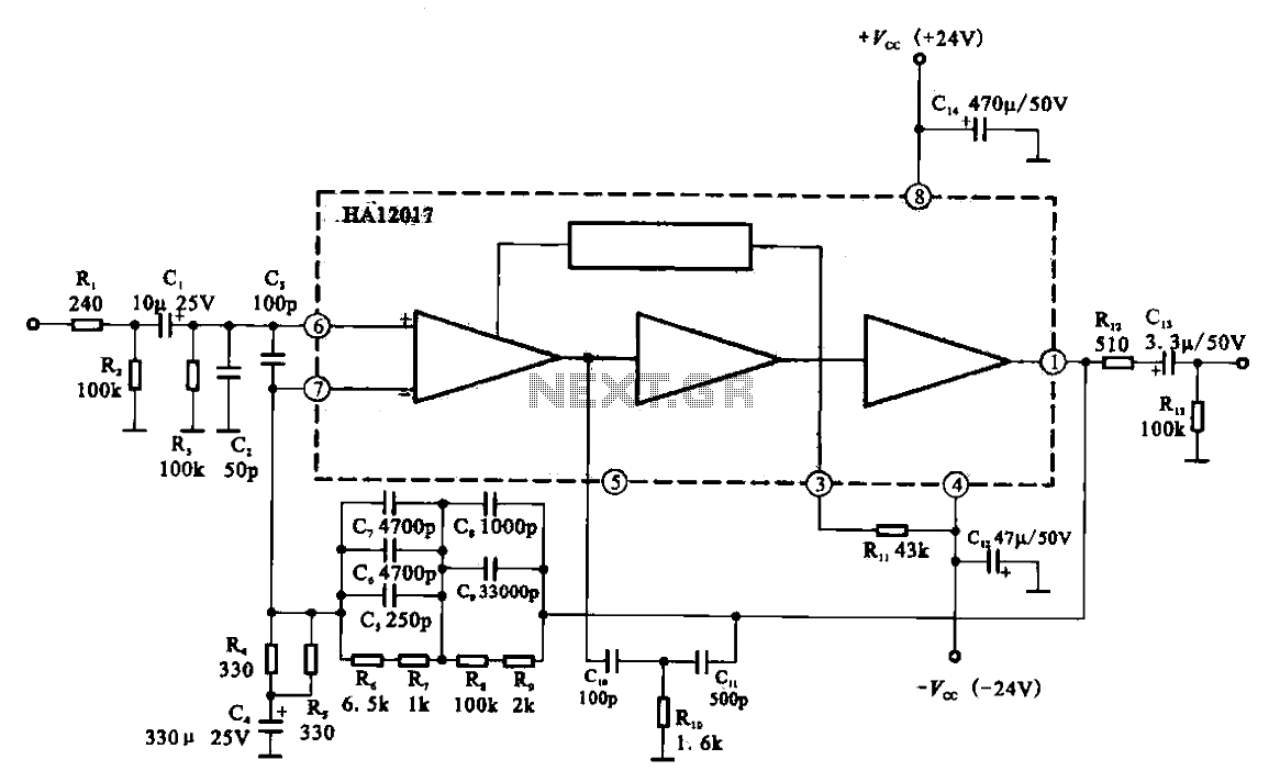
Low-noise preamplifier circuit. This circuit demonstrates a typical low-noise preamplifier design, which can be utilized to amplify signals from sources such as magnetic heads and microphones within audio applications. The input signal is coupled through a capacitor and subsequently...
The following circuit illustrates a portable NiCd battery charger circuit diagram. The portable battery charger is designed to facilitate the charging of nickel-cadmium batteries. The portable NiCd battery charger circuit typically consists of several key components, including a transformer, rectifier,...
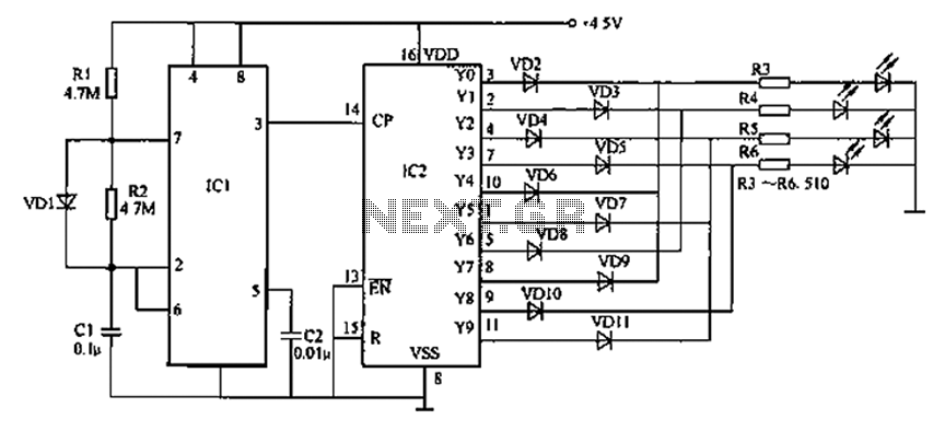
AC level meters, such as VU meters, and DC level meters, such as signal meters, are used for measuring electrical signal levels. These devices feature a display consisting of nine red or green LEDs that represent the input level...