
Micro Power AM Broadcast Transmitter

The circuit employs the 74HC14 hex Schmitt trigger inverter due to its ability to provide a clean square wave output, which is essential for driving the subsequent transistor stage effectively. The Schmitt trigger's hysteresis characteristics enhance the stability of the oscillator, allowing it to maintain consistent frequency output even in the presence of noise.
In the VFO configuration, the oscillator frequency is determined by the RC time constant of the capacitor and resistor network. The choice of a 100pF capacitor allows for a range of operating frequencies, which can be adjusted by varying the resistance in the circuit. This flexibility makes the circuit suitable for applications requiring frequency modulation or tuning.
The output from the 74HC14 is connected to the base of a small signal transistor, which operates in class C mode. In this configuration, the transistor conducts for less than half of the input signal cycle, resulting in high efficiency and the ability to amplify high-frequency signals. The class C amplifier is particularly effective in RF applications where signal amplification is required without significant power loss.
The overall design of this circuit is compact and efficient, making it ideal for various electronic applications, including signal generation and amplification in communication devices. Proper selection of components, particularly the resistor and capacitor values, is crucial for achieving the desired frequency response and stability in the oscillator output.In this circuit, a 74HC14 hex Schmitt trigger inverter is used as a square wave oscillator to drive a small signal transistor in a class C amplifier configuration. The oscillator frequency can be either fixed by a crystal or made adjustable (VFO) with a capacitor/resistor combination.
A 100pF capacitor is used in place of the crystal for VFO operation 🔗 External reference
Related Circuits
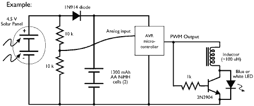
This example demonstrates the PWM (pulse-width modulation) output of a microcontroller controlling a Joule Thief style voltage booster to power a white LED. The circuit described utilizes a microcontroller to generate a PWM signal, which is an effective method for...

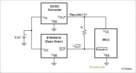
A capacitor step-down DC power supply circuit is presented. This circuit eliminates the need for power transformers, utilizing capacitive voltage drop rectification and regulation, which significantly reduces the overall size of the circuit. The circuit includes a capacitor step-down...
STMicroelectronics introduces the STV0288, its latest DVB and DIRECTV QPSK digital receiver, which adds blind scan capability and DiSEqC 2.0 to the industry-leading STV0299 and provides a cost reduction path for new products. The STV0288 is a sophisticated digital receiver...

This circuit functions as a voice transmitter utilizing a pair of BC548 transistors. While these transistors are not specifically designed for RF applications, they still yield satisfactory performance. An ECM microphone insert from Maplin Electronics, order code FS43W, is...
The USB charger power supply is designed for use in MP3 and MP4 chargers. It accepts an input of AC 160-240V at 50/60Hz and has a rated output of DC 5V at 250mA. For applications requiring a long-term higher...
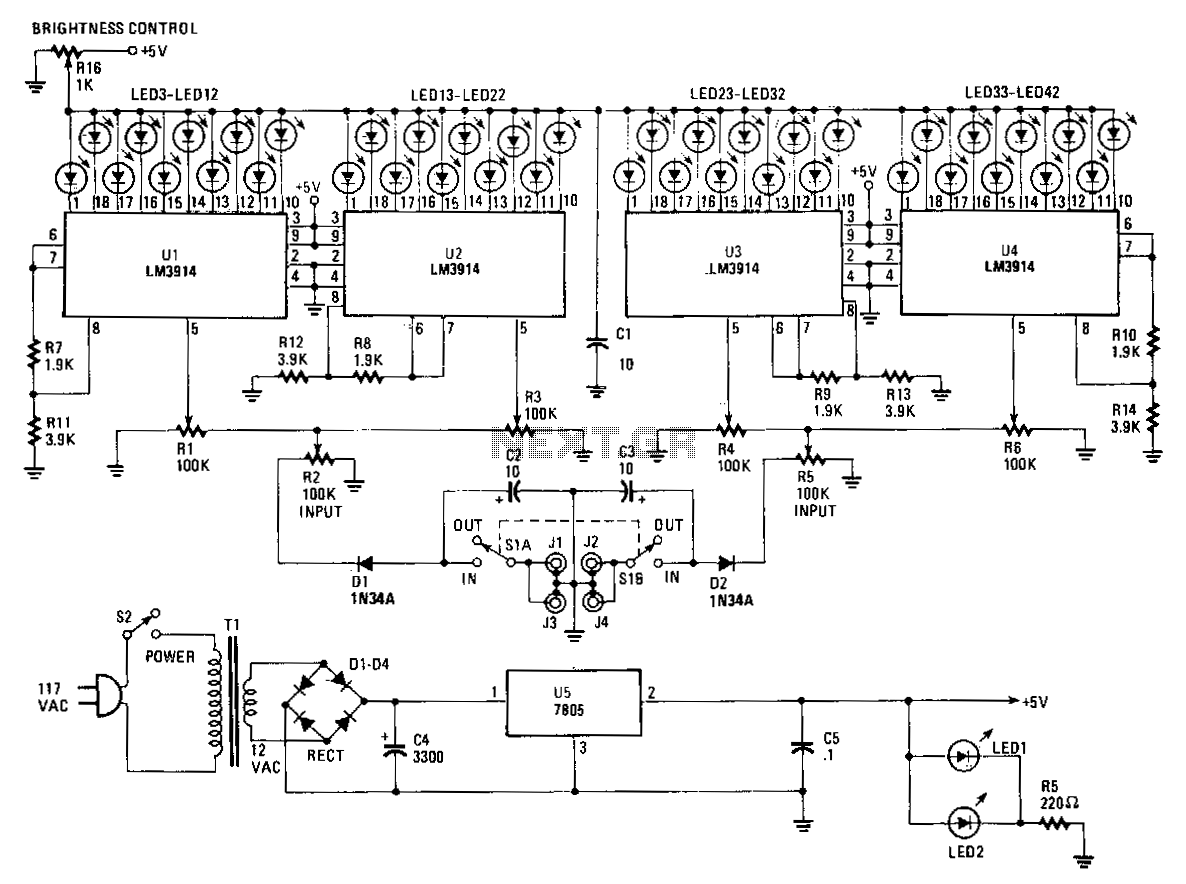
The Stereo Power Meter consists of two identical circuits and a power supply. Each circuit features two LM3914 display chips, which include 10 voltage comparators, a 10-step voltage divider, a reference voltage source, and a mode-select circuit that allows...