
IR Remote Control Switch
The circuit utilizes a relay as the primary switching element, enabling the control of high-power devices through low-power signals. The key components of the circuit include a relay, a power supply, a transistor, and a remote control receiver module.
The operation begins with the remote control, which sends an infrared (IR) signal to the receiver module. The receiver module is connected to a transistor that acts as a switch. When the IR signal is detected, the receiver outputs a signal that turns on the transistor. This allows current to flow through the relay coil, energizing the relay and closing its contacts. Consequently, the connected electrical device is powered on.
To turn off the device, the remote control sends another signal, which is again received by the module. This signal deactivates the transistor, cutting off the current to the relay coil. As a result, the relay opens its contacts, disconnecting the power supply to the device.
The circuit can be powered using a standard AC or DC power supply, depending on the relay specifications. It is important to ensure that the relay used can handle the voltage and current requirements of the connected device. Additionally, proper isolation techniques should be employed to protect the low-voltage components from high-voltage spikes that may occur when switching inductive loads.
This remote control switching circuit is versatile and can be used for various applications, including controlling lights, fans, and other household appliances, providing convenience and energy efficiency.Today we are going to explain about a simple circuit which is used to switch on/off any electrical device remotely through a relay using the normal TV/VCR.. 🔗 External reference
Related Circuits
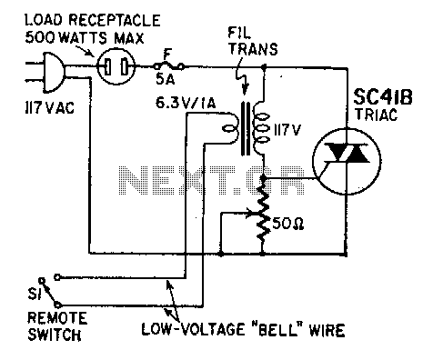
This circuit facilitates power control without the need for line-voltage switch leads. The primary winding of a 6-volt filament transformer is connected between the gate and one of the main terminals of a triac. The secondary winding is linked...
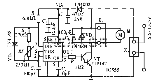
The circuit operates using pulse position modulation, which is a method distinct from the more commonly utilized pulse width modulation for speed control. A 555 timer is employed as a square wave modulator, generating output pulses with a fixed...
The transmitter is shown and although straightforward, there are a couple of tricks that I had to incorporate to minimise battery drain during standby. Although the PIC quiescent current is only 200uA, that will still flatten a pair of...
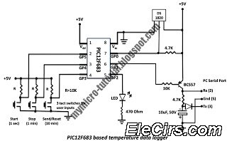
A data logger is a device that records measurements over time. The measurements could be any physical variable like temperature, pressure, voltage, humidity, etc. This project describes how to build a mini logger that records surrounding temperature. A data logger...
The disadvantage of infrared or wireless remote control is that the remote transmitter is often misplaced. This circuit design offers a way to control ... This circuit design addresses the common issue of misplaced remote transmitters in infrared or wireless...
The Allegro ACS75x family of Current Sensors offers cost-effective and accurate solutions for current sensing in industrial, automotive, commercial, and communications systems. The device package facilitates easy implementation by the customer. Typical applications encompass motor control, load detection and...