
ir remote control tester

The circuit consists of a few key components: an IR receiver IC, a piezo buzzer, and supporting passive components such as resistors and capacitors. The IR receiver IC detects infrared signals emitted by the remote control. When the remote is activated, it sends out a modulated IR signal that the receiver IC picks up. The output of the IR receiver IC is a digital signal that indicates whether the IR signal is present.
The piezo buzzer serves as an auditory indicator of the circuit's operation. When the IR receiver detects a signal, it activates the buzzer, producing a sound that confirms the receipt of the infrared command. This immediate feedback allows users to quickly ascertain whether the remote control is functioning correctly.
In terms of power requirements, the circuit typically operates on low voltage, making it suitable for battery operation. The design emphasizes simplicity and accessibility, allowing users to test remote controls without the need for complex setups or additional testing devices.
Overall, this small circuit is an effective and user-friendly solution for testing infrared remote controls, offering portability and ease of use in a variety of settings.This small circuit is ideal for checking the basic operation of an infrared remote control unit. The circuit is based on the brilliantly simple idea of connecting a piezo buzzer directly to an IR receiver IC. This method is almost as simple as connecting a photodiode directly to the input of an oscilloscope, but has the advantage that no oscilloscope is needed: the compact unit is always ready to use and much easier to carry around than bulky test equipment..
🔗 External reference
Related Circuits

The passive tone control circuit is designed to adjust the bass without expansion, utilizing resistors (R) and capacitors (C). It functions as a frequency filter and is easy to construct, requiring no external power supply. This circuit can be...
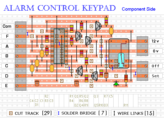
This keypad is designed for use with a modular burglar alarm system but can also be applied in various other applications. Pressing a single key will activate the relay, while entering a four-digit code of your choice will deactivate...
Testing whether a transistor is shorted or open is typically performed using an ohmmeter. The test involves checking if current can flow between the base and emitter or the collector. To effectively test a bipolar junction transistor (BJT) for shorted...
A phase-locked loop (PLL) is widely utilized in telecommunications, control systems, and various other electronic applications. PLLs can be employed to demodulate frequency-modulated (FM) signals and generate a stable output frequency. A phase-locked loop is an essential feedback control system...
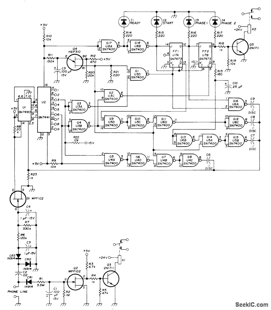
A repeater or other unattended equipment can be activated or deactivated using a standard telephone. The process involves calling the remote station, allowing it to ring three times, hanging up, waiting for 20 seconds, redialing the number, and letting...
LBl690 is a three-phase brushless DC motor drive control integrated circuit manufactured by Sanyo, a Japanese company. It is extensively utilized in both domestic and imported applications for broken wind and fresh air conditioning systems that require brushless DC drive...