
Simple Transistor Tester Using 555 IC

To effectively test a bipolar junction transistor (BJT) for shorted or open conditions, an ohmmeter is utilized to measure the resistance across various junctions of the transistor. A BJT has three terminals: the emitter, base, and collector. The two primary junctions to test are the base-emitter (BE) and base-collector (BC) junctions.
1. **Base-Emitter Junction Test**:
- Set the ohmmeter to the resistance measurement mode.
- Connect the positive lead to the base and the negative lead to the emitter. A typical reading should show a low resistance (usually in the range of a few hundred ohms) in one direction (forward bias) and a very high resistance (open circuit) in the opposite direction (reverse bias).
- If the reading is low in both directions, the base-emitter junction is shorted. Conversely, if the resistance is high in both directions, the junction may be open.
2. **Base-Collector Junction Test**:
- Similarly, connect the positive lead to the base and the negative lead to the collector. The expected behavior is identical to that of the base-emitter junction. A low resistance reading in one direction indicates a functional junction, while a high resistance reading in both directions suggests an open or faulty junction.
- A shorted base-collector junction will show low resistance in both directions.
3. **Emitter-Collector Junction Test**:
- It is also beneficial to check the emitter-collector junction directly. Connect the positive lead to the emitter and the negative lead to the collector. The resistance should be high in both directions if the transistor is functioning correctly. A low reading in either direction indicates a short circuit.
In summary, the ohmmeter testing method provides a straightforward approach to determining the operational status of a transistor. By assessing the resistance across the critical junctions, one can ascertain if the transistor is shorted, open, or functioning normally. Proper testing is essential for ensuring reliable operation in electronic circuits where transistors are employed.Testing whether a transistor is shorted or open usually done by ohm meter. You test if the base to emitter? or collector permit a current flow in one. 🔗 External reference
Related Circuits
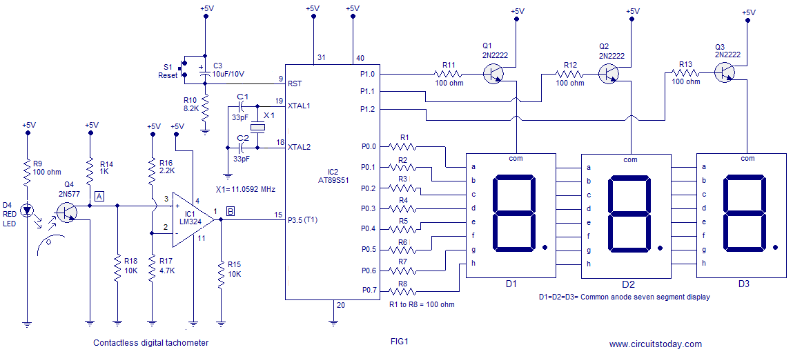
A three-digit contactless digital tachometer utilizing an 8051 microcontroller is presented for measuring the revolutions per second of rotating objects such as wheels, discs, or shafts. The tachometer can measure up to a maximum of 255 revolutions per second...
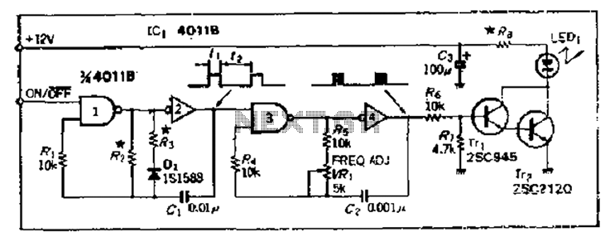
The 4000 Series 4011B is a NAND gate used in conjunction with a 4AI NAND gate circuit group to create two loops of an unstable multivibrator. The first NAND gate and the second NAND gate operate at approximately 1...
The circuit below illustrates generating a single positive pulse which is delayed relative to the trigger input time. The circuit is similar to the one above but employs two stages so that both the pulse width and delay can...
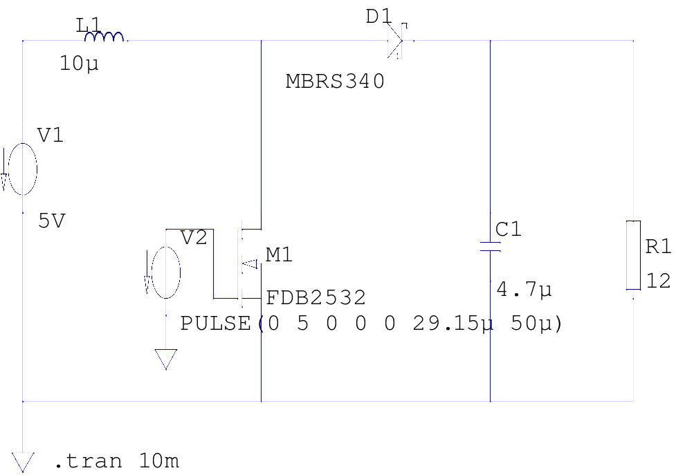
The supply voltage is 5V, and the goal is to increase it to 12V with a load current of 1A, resulting in an output power of 12W. A switching frequency of 20kHz has been selected, requiring a duty cycle...
The PR4403 is an advanced version of the PR4402 40mA LED driver. It features an additional input known as LS, which can be activated by pulling it low to illuminate the LED. This functionality simplifies the construction of an...
The circuit was designed to create a high-impedance voltmeter capable of measuring Direct Current (DC) voltages across various types of circuits. The high-impedance voltmeter circuit typically employs operational amplifiers (op-amps) configured in a non-inverting arrangement to ensure minimal loading on...