
IR S/PDIF Transmitter

The S/PDIF (Sony/Philips Digital Interface) protocol is widely employed for transmitting high-quality digital audio signals between devices such as CD players, digital audio converters, and home theater systems. The two primary transmission methods utilized in S/PDIF are coaxial and optical, each offering distinct advantages.
Coaxial transmission utilizes a 75-ohm coaxial cable, which consists of a central conductor surrounded by an insulating layer and an outer conductive shield. This configuration minimizes signal loss and electromagnetic interference, making it suitable for high-fidelity audio applications. The coaxial cable typically connects to RCA jacks on the audio equipment, ensuring a secure and reliable connection. The electrical signal transmitted through the coaxial cable is a voltage-based representation of the audio data, which can be easily processed by compatible digital-to-analog converters (DACs).
On the other hand, Toslink optical transmission employs fiber optic cables to transmit audio signals as pulses of light. This method offers the advantage of electrical isolation, which eliminates the risk of ground loop noise and interference from nearby electronic devices. Toslink connectors are typically used for this type of connection, allowing for a straightforward plug-and-play setup. The optical modules convert the digital audio signal into light pulses, which travel through the fiber optic medium and are then converted back into an electrical signal by the receiving device's optical receiver.
Both transmission methods support various audio formats, including stereo PCM and multi-channel audio formats such as Dolby Digital and DTS. The choice between coaxial and Toslink depends on the specific requirements of the audio system, including the distance between devices, the potential for interference, and the available connection ports. Proper selection and implementation of these transmission methods are crucial for achieving optimal audio performance in digital audio systems.The best-known ways to transmit a digital audio signal (S/PDIF) are to use a standard 75? coaxial cable or Toslink optical modules with matching optical c.. 🔗 External reference
Related Circuits
This is a compact yet powerful FM transmitter featuring three RF stages and an audio preamplifier for enhanced modulation. It delivers an output power of 4 Watts and operates on 12-18 VDC, making it highly portable. This project is...
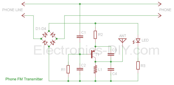
This phone FM transmitter connects in series to a telephone line and transmits telephone conversations over the FM band when the telephone handset is picked up. The transmitted signal can be tuned by any FM receiver. The circuit includes...

An FM radio generates an interference signal that can be detected on another FM radio tuned 10.7 MHz higher than the original. A 50 kΩ potentiometer is used to adjust the modulation level to its maximum without introducing distortion....

3V FM Transmitter Circuit. This project provides the schematic and parts list needed to construct a 3V FM transmitter. This FM transmitter is one of the simplest and most basic transmitters to build, offering a useful transmitting range. The 3V...
Most IR remotes operate effectively within a range of 5 meters. The complexity of the circuit increases when designing the IR transmitter for reliable operation over longer distances, such as 10 meters. To extend the range from 5 meters...
This is the basic FM transmitter that I built. In theory, according to electronics, it shouldn't work but works fine and is very sensitive. It can transmit the signal up to 45 yards (about 40 meters). A sensitive FM...