
Fm Radio Transmitter Circuit

The described FM radio circuit operates on the principle of frequency modulation, where the audio signal alters the frequency of the carrier wave. The interference signal generated by the first FM radio can be captured by a second radio that is tuned to a frequency offset of 10.7 MHz. This offset is significant as it falls within the FM broadcast band, allowing for clear reception of the modulated signal.
The inclusion of a 50 kΩ potentiometer allows for fine-tuning of the modulation depth. Adjusting this component ensures that the transmitted signal maintains clarity without distortion, which is crucial for high-fidelity audio transmission. The RC network, composed of resistors and capacitors, serves dual purposes: it filters the signal to enhance audio quality and isolates the DC components, preventing unwanted bias from affecting the modulation process.
The component values in the RC network should be selected based on the desired frequency response and the specific characteristics of the radios involved. It is essential to note that variations in component values may be necessary depending on the specific radio models being used, as different radios may have different sensitivities and impedances.
When attempting to receive the interference signal, both radios must be tuned to frequencies that are free from other broadcasts. If the first radio is transmitting at a certain frequency, the second radio must be tuned to a frequency that is exactly 10.7 MHz higher or lower, depending on which direction yields a clearer signal. This frequency separation is critical to avoid interference from other stations, which could result in overlapping audio signals.
In summary, this FM radio circuit setup demonstrates the principles of frequency modulation and interference signal detection, utilizing a potentiometer for modulation control and an RC network for signal fidelity and isolation. Proper tuning and selection of component values are essential for successful operation and optimal audio quality. An FM radio generates an interference signal that can be picked up on another FM radio tuned 10.7 MHz above the first one. The 50-k0 potentiometer adjusts the modulation level to maximum without distortion. The RC network improves the fidelity of the transmitted signal and provides dc isolation. The component values shown are provided as a starting point. They can vary somewhat for different radios. Note that if you can`t get the signal at 10.7 MHz above the frequency setting of the first radio, try tuning at 10.7 MHz below.
Also, note that both tuned frequencies must be unused. Otherwise, you will hear your audio on top of the audio that is already there. You might have to play with both frequencies until you find two blank spots that are 10.7 MHz apart.
Related Circuits
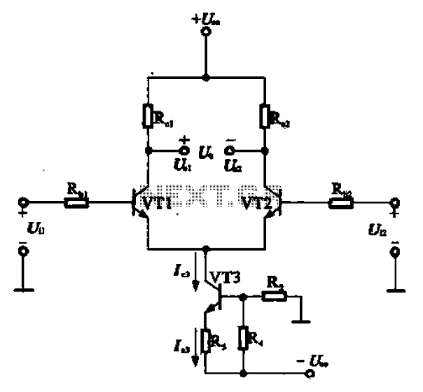
A constant current source is utilized in the differential amplifier circuit, which includes an emitter resistor. In this configuration, an increase in the output voltage (Ua) is not desirable. To ensure that Ua remains stable, the supply voltage (Ucc)...
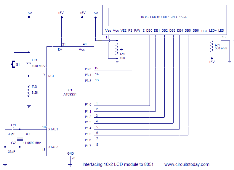
Interfacing a 16x2 alphanumeric LCD module with the AT89S51 microcontroller. The circuit diagram, theory, and program are included. JHD162 LCD module pinout and commands are provided. The integration of a 16x2 alphanumeric LCD module with the AT89S51 microcontroller involves several...
The loop can be any type of hookup wire, with a maximum resistance of about 90K. Using very thin wire (40AWG, for example) will create a highly sensitive trip wire, but will reduce the distance it can be strung...
P1 47K logarithmic potentiometer; P2, P3 47K linear potentiometers; R1, R3, R5 4.7K 1/4W resistors; R2 22K 1/4W resistor; R4 1M 1/4W resistor; R6 1.8K 1/4W resistor; R7 560Ω 1/4W resistor; C1, C4, C5, C7 10 µF 63V electrolytic...

When the preset is set to its maximum, the LED flashes at a rate of approximately once every half second. This rate can be increased by raising the capacitor value from 10µF to a higher value. For instance, if...
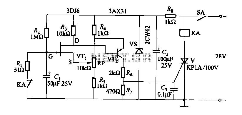
FET relay circuit 2 is essentially a JS-20 time relay circuit. When the switch SA is open, the relay device KA remains in the released state. Once switch SA is closed, the delay period begins. After a specified duration,...