
ir sensors from scratch line follower

To design a sensor circuit that effectively utilizes the potential divider principle, it is essential to consider the relationship between the sensor resistance and the chosen resistor R1. The potential divider configuration allows the voltage output to vary significantly based on the light conditions, which is critical for applications requiring precise light detection.
In this setup, Rsensor will vary between two distinct values: Rsensor = a (high resistance) when no light is detected and Rsensor = b (low resistance) when exposed to light. The output voltage at point 2', derived from the voltage divider formula, can be expressed as:
Vout = (Rsensor / (Rsensor + R1)) * Vin
Where Vin is the input voltage supplied to the divider. When light is present, the lower resistance (b) will yield a higher voltage at point 2', while the higher resistance (a) in darkness will result in a lower voltage.
To optimize the circuit for maximum voltage swing, careful selection of R1 is crucial. It should be chosen to ensure that the output voltage at point 2' demonstrates a significant difference between the two states, allowing for clear differentiation in the ADC readings. This is particularly important in digital applications where accurate light level detection is necessary for proper system functioning.
In summary, the design of this sensor circuit hinges on the proper selection of R1 to maximize the voltage change at point 2' under varying light conditions, ensuring effective performance in applications utilizing ADCs for signal processing.To get a good voltage swing, the value of R1 must be carefully chosen. If Rsensor = a when no light falls on it and Rsensor = b when light falls on it. The difference in the two potentials is: in presence of light and a very large resistance in absence of light. We have used this property of the sensor to form a potential divider. The potential at point 2` is Rsensor / (Rsensor + R1). Again, a good sensor circuit should give maximum change in potential at point 2` for no-light and bright-light conditions. This is especially important if you plan to use an ADC in place of the comparator To get a good voltage swing, the value of R1 must be carefully chosen.
If Rsensor = a when no light falls on it and Rsensor = b when light falls on it. The difference in the two potentials is: 🔗 External reference
Related Circuits
Commonly used 3-pin linear voltage regulators, such as the LM317, typically cannot handle input voltages exceeding approximately 30V. The LR8A from Supertex Inc is a new adjustable three-pin regulator that can accept input voltages up to 450V and can...
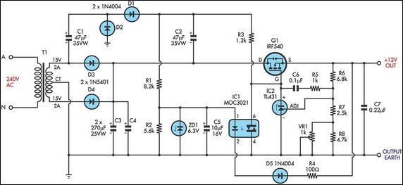
This circuit is a MOSFET-based linear voltage regulator with a voltage drop as low as 60mV at 1A. It utilizes a 15V-0-15V transformer and an IRF540 N-channel MOSFET (Q1) to deliver a regulated 12V output. The required gate drive...
This is the most simple phone busy indicator is possible with only three parts. Connect the circuit so that the green light illuminates when the line is free. If the receiver than the hook, the green LED light is...

Author Jim Walker describes a very low-cost analog delay line circuit using components such as the LM311 comparator and 74HC74 D flip-flop. The analog delay line circuit presented by Jim Walker utilizes the LM311 comparator and the 74HC74 D flip-flop...
If there is a suspicion that the broadband speed (DSL) is slower than expected, it may be due to incorrect polarity in the phone wall socket. A simple and inexpensive device can be built to determine if the wiring...
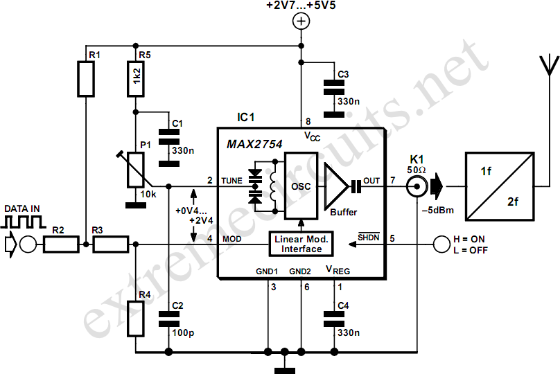
High-frequency voltage-controlled oscillators (VCOs) are challenging to construct, which is why Maxim has developed the integrated 1.2 GHz oscillator, the MAX2754. The center frequency is adjustable via the TUNE input, while a linear modulation input allows for frequency modulation....