
Low-Cost Audio Delay Line Uses 1-Bit ADC

The analog delay line circuit presented by Jim Walker utilizes the LM311 comparator and the 74HC74 D flip-flop to achieve a cost-effective solution for signal delay applications. The LM311 is a versatile voltage comparator that can be employed to detect the threshold levels of an input signal and produce a corresponding output. The 74HC74 is a dual D-type flip-flop, which can be used for storing binary information and is capable of providing edge-triggered operation.
In this circuit, the LM311 is configured to compare the input signal against a reference voltage. When the input signal exceeds the reference level, the output of the LM311 changes state, which can be used to trigger the 74HC74 flip-flop. The flip-flop then captures the input signal state at the moment of the triggering event, effectively introducing a delay based on the clock frequency applied to the flip-flop.
The design can be adjusted to modify the delay time by changing the clock frequency or by introducing additional components, such as resistors and capacitors, that influence the timing characteristics. This flexibility allows for a wide range of applications, including audio signal processing, data communication, and pulse width modulation.
Overall, the combination of the LM311 comparator and the 74HC74 D flip-flop in this analog delay line circuit provides a simple yet effective means of achieving controlled signal delays at a minimal cost, making it suitable for various electronic projects and applications.Author Jim Walker describes a very low cost analog delay line circuit using parts such as the LM311 comparator and 74HC74 D flip-flop. 🔗 External reference
Related Circuits

This circuit provides emergency lighting during a power outage. The phototransistor should be positioned to maximize the coupling of both neon light and ambient light into the pellet, without allowing self-illumination from the 6-V lamp. Many circuits of this...
High Quality very simple unit - No need for a preamplifier. Can be directly connected to CD players, tuners and tape recorders. Don't exceed 23 + 23V supply. Q3 and Q4 must be mounted on heatsink. D1 must be...

The timing interval is initiated by applying power and is determined by the resistor-capacitor (RT-CT) combination. At the end of the interval, a unijunction transistor triggers a silicon controlled rectifier (SCR) to apply nearly the full supply voltage to...
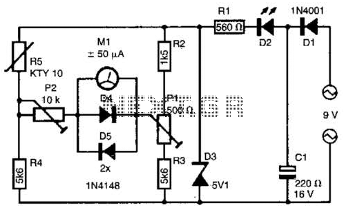
The telephone line tester comprises a meter used to measure line voltage in both the on-hook and off-hook states, three resistors (including one variable resistor), a pushbutton switch, and a modular telephone connector. When the circuit is connected to...
This circuit utilizes the power MOSFET IRF840 for a 60-watt linear amplifier. The IRF series of power transistors are available in various voltage and current ratings. The described circuit employs the IRF840, which is a high-voltage N-channel MOSFET, suitable for...
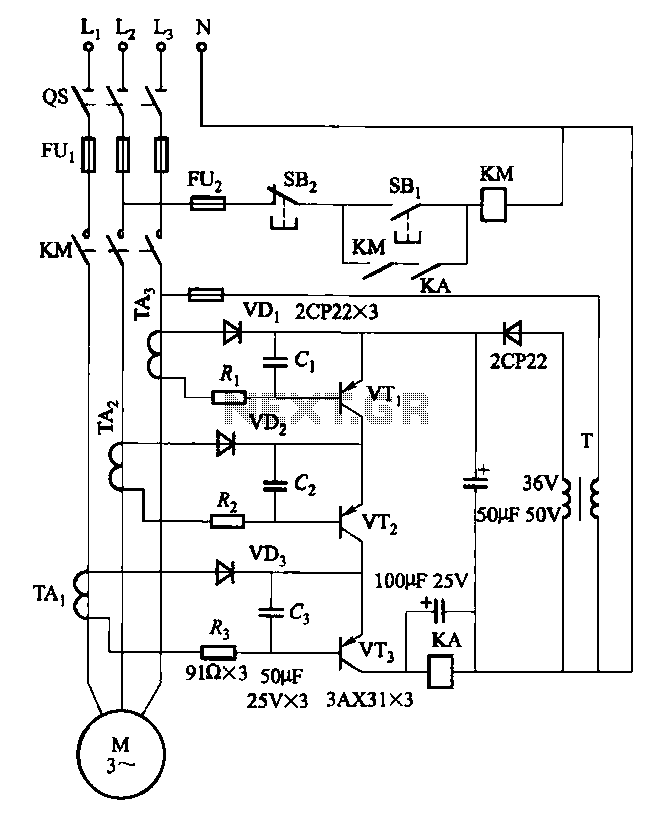
Drawing transistors that comprise the gate VTi, VT2, VT3, and similar components. The schematic involves a configuration of transistors designated as VTi, VT2, and VT3, which are integral to forming a gate structure. These transistors are typically arranged in a...