
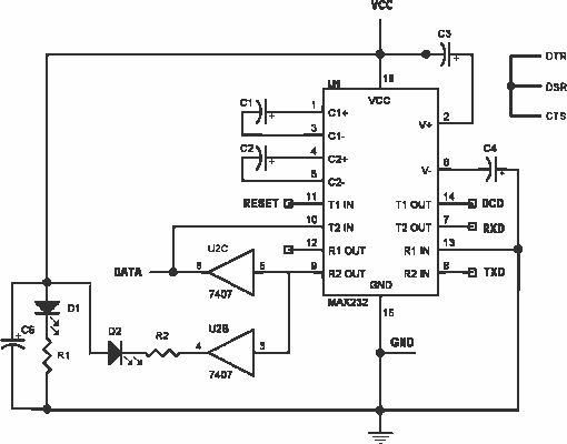
ISOLATED FULL DUPLEX RS232C INTERFACE

The self-powered interface circuit is designed to ensure robust electrical isolation between a computer's serial port and connected equipment. This is critical in applications where the connected devices may operate at different voltage levels or where ground potential differences could create harmful earth loops.
The circuit utilizes two key signals from the serial port: Data Terminal Ready (DTR) and Request to Send (RTS). The DTR signal provides a negative supply voltage, while the RTS signal supplies the positive voltage necessary for circuit operation. This configuration allows the circuit to be powered directly from the serial port without the need for an external power source, simplifying the design and enhancing portability.
Electrical isolation is achieved through the use of opto-isolators or isolation transformers, which separate the TxD (transmit data) and RxD (receive data) lines from the PC. This isolation prevents any high voltages present in the connected equipment from affecting the computer, thereby protecting sensitive components from damage.
The schematic representation of the circuit typically includes connector K1, which interfaces with the PC's serial port. The TxD and RxD lines are routed through the isolation components, ensuring that the data transmission remains intact while maintaining electrical separation. Additional components such as capacitors and resistors may be included to filter noise and stabilize the power supply.
Overall, this self-powered isolation circuit is essential for protecting computers in industrial environments or applications where equipment operates at different voltage levels, ensuring safe and reliable data communication.This self powered interface circuit electrically isolates the TxD and RxD lines from the PC serial port and protect the PC from direct connection to hazardous voltages. The isolator is intended to provide electrical isolation between a computer and the equipment connected to its serial port.
This can be necessary when the target system works at a completely different voltage level, or when earth loops must be avoided. Figure 1 shows how the electrical isolation is achieved. Connector K1 is linked to the serial port of the PC, power to the PC side of the circuit is derived from the signal lines DTR and RTS. Positive supply is derived from RTS and -ve one from the DTR li 🔗 External reference
Related Circuits
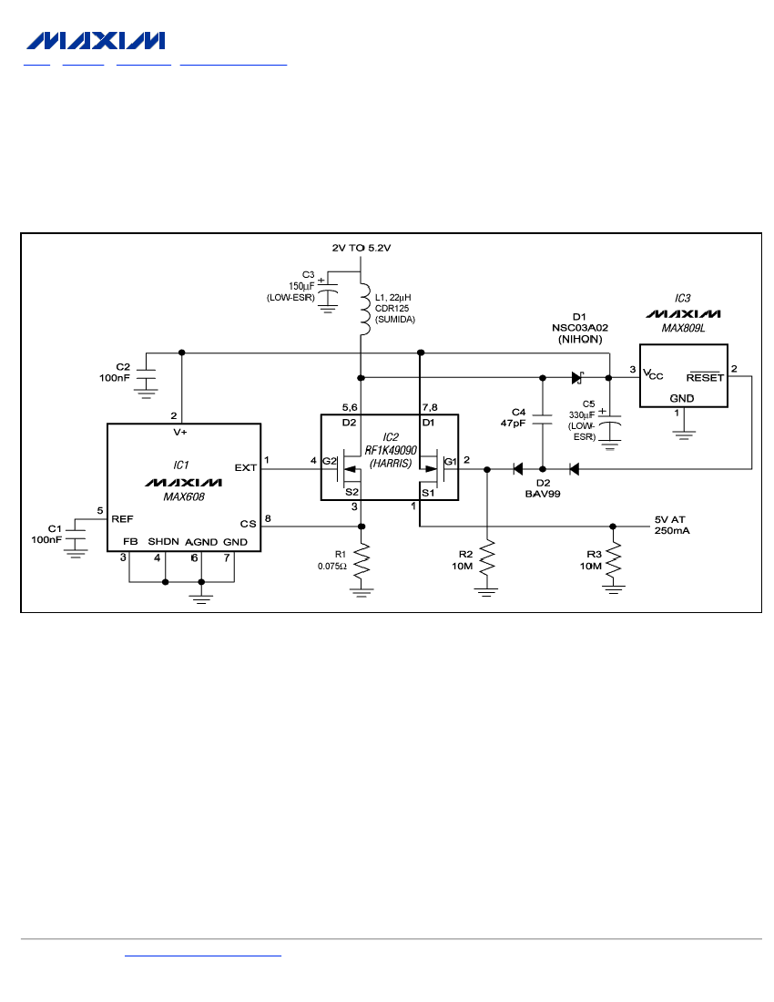
To ensure a full-load start-up, the additional circuitry in this regulated boost converter disconnects the load until the output voltage reaches regulation. Proper operation necessitates a gate-drive voltage adequate to maintain low on-resistance in the switching MOSFET; however, during...
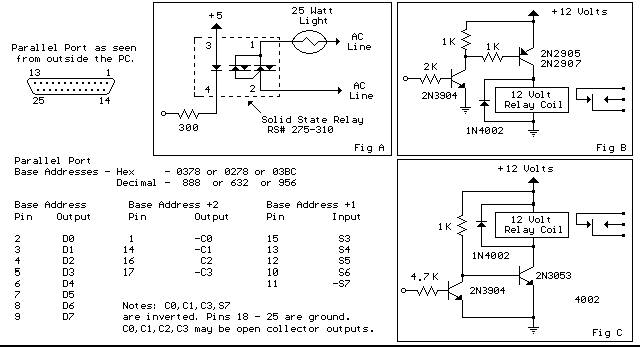
Below are three examples of controlling a relay from the PC's parallel printer port (LPT1 or LPT2). Figure A shows a solid-state relay controlled by one of the parallel port data lines (D0-D7) using a 300-ohm resistor and a...
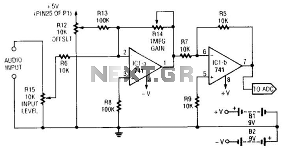
This simple general-purpose driver for an analog/digital converter uses two 741 IC devices with adjustable gain and offset. Other op-amps might be substituted, but some circuit adjustments might be needed. The circuit consists of two operational amplifiers (op-amps) from the...
This smartcard adapter follows exactly the specification ISO 7816. Also, the protocol is the "asynchronous half duplex T=0 protocol" with "active low reset" and "inverse convention" as defined in this standard. The following description may be used in order...
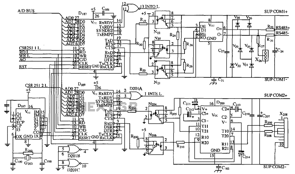
As shown in the figure, D187 is a universal asynchronous receiver-transmitter (UART). Its RX/TX signals are received through optocouplers N21, N22, and N29, facilitating RS-485 communication. The interface receiver/transmitter D28 and microprocessor D211 are completely optically isolated. D197 serves...

This joystick model was introduced by IBM alongside their first IBM PC computer. It is a basic analog joystick featuring two buttons. The original joystick interface included a circuit for connecting two joysticks but only had one joystick connector....