
JFET Nixie Tube Driver

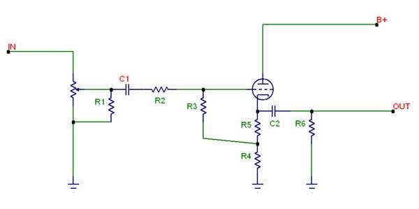
The nixie tube driver circuit is designed to control the operation of nixie tubes, which are gas-discharge display devices used for numerical readouts. The 2N3684 transistor is selected for its ability to handle the required voltage range effectively, ensuring reliable switching and illumination of the nixie tube segments.
In this circuit, the 2N3684 acts as a switch, allowing or interrupting the flow of current to the nixie tube based on TTL (Transistor-Transistor Logic) or DTL (Diode-Transistor Logic) input signals. The circuit typically consists of a series of resistors to limit the current flowing through the nixie tube and to protect the transistor from excessive current. Additionally, capacitors may be included for noise filtering and stability.
The design may also incorporate a microcontroller or a logic gate to generate the control signals, enabling the display of various numerals by selectively activating the corresponding segments of the nixie tube. Proper biasing of the transistor is crucial for ensuring that it operates within its safe limits while switching efficiently.
Overall, this driver circuit is an essential component in applications requiring numerical displays, combining the vintage aesthetic of nixie tubes with modern electronic control techniques.This is a driver circuit for nixie tube. This circuit uses 2N3684 as nixie tube drivers because its Vp is 2-5 volts which is ideally matches TTL-DTL logic.. 🔗 External reference
Related Circuits
There is a modification to the RC delay circuits that some may want to consider. If a shorter discharge time is desired, this modification enables the circuit to restart more quickly. The modification to the RC delay circuit involves adjusting...
Attached are three captures from a L297/L298 board using the same motor at 500, 750, and 900 steps per second on a 36V supply, wired in bipolar parallel (coil resistance = 3.2 ohms). This shows the A-enable signal (blue)...
The following diagram is for the main circuit of the motor driver. A testing version is shown near the end of this page. It is laid out differently and shows the SN7474 in logic block form and LEDs are...
By sufficiently lowering the output impedance of a circuit and supplying enough current to drive cables, it avoids the issues faced by passive designs. This approach seems to address many of the inherent problems in both active and passive...
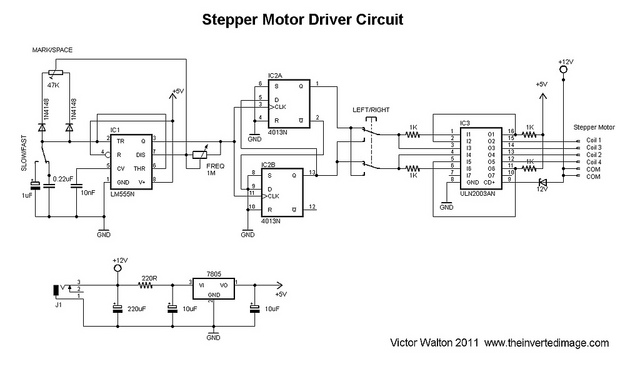
The commonly used 555 timer is configured for a variable mark/space ratio, which is essential for this application. Additionally, two D-type flip-flops (4013) are employed to provide the necessary count for the ULN2003 stepper motor driver. ULN2003 components may...
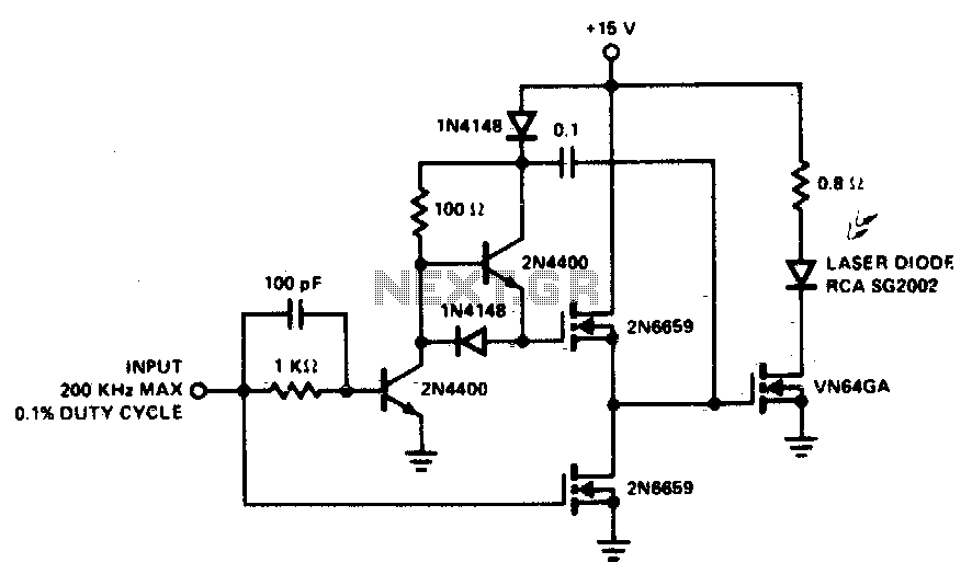
A faster driver can supply higher peak gate current to switch the VN64GA very quickly. The circuit uses a VMOS totem pole stage to drive the high power switch. The described circuit employs a high-speed driver to enhance the switching...