
Simple B+ delay circuit for tube power amp

The modification to the RC delay circuit involves adjusting the resistor-capacitor (RC) time constant to achieve a shorter discharge time. This can be accomplished by either reducing the resistance or the capacitance in the circuit. The time constant (τ) is defined as τ = R × C, where R represents resistance in ohms and C represents capacitance in farads. By decreasing either of these values, the discharge time can be minimized, leading to a faster reset of the circuit.
For practical implementation, consider using a potentiometer in place of a fixed resistor. This allows for fine-tuning of the resistance value, enabling precise control over the discharge time. Additionally, selecting a capacitor with a lower capacitance value will also contribute to a quicker discharge. However, care must be taken to ensure that the new values do not adversely affect the circuit's performance or stability.
When modifying the RC delay circuit, it is essential to analyze the impact of these changes on the overall functionality. The discharge curve should be examined to ensure that it meets the desired specifications. Furthermore, it may be beneficial to simulate the circuit using software tools to visualize the effects of the modifications before implementing them in a physical prototype.
In summary, the modification to achieve a shorter discharge time in RC delay circuits can enhance the responsiveness of the system, making it suitable for applications where rapid circuit restarts are necessary.There is a mod to the RC delay circuits some of you may want to consider. If you wish to have a shorter discharge time so that the circuit restarts.. 🔗 External reference
Related Circuits
With this circuit we can create a altered sound of siren. The oscillator IC1a-b is constituted by two gates NAND, oscillating in very low frequency. This oscillation drive the IC2, that is a electronic switch, which opens and closes...
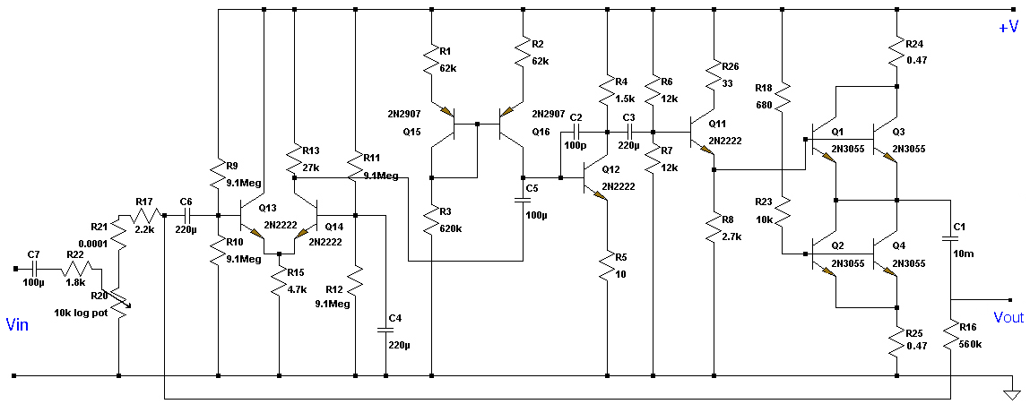
This Class A preamplifier features a symmetrical design. The input differential stages utilize dual transistors, T1 and T2. Polarization correction is crucial due to amplification discrepancies and is managed by transistor T12. Potentiometer P2 adjusts the output voltage to...
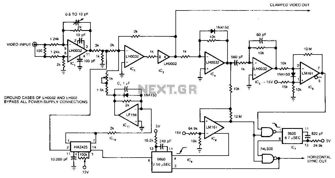
The circuit utilizes a track-and-hold amplifier in a closed-loop configuration to clamp the back-porch voltage of a standard video waveform to 0 V. The outputs of the circuit include a clamped composite video signal and a TTL-level horizontal blanking...
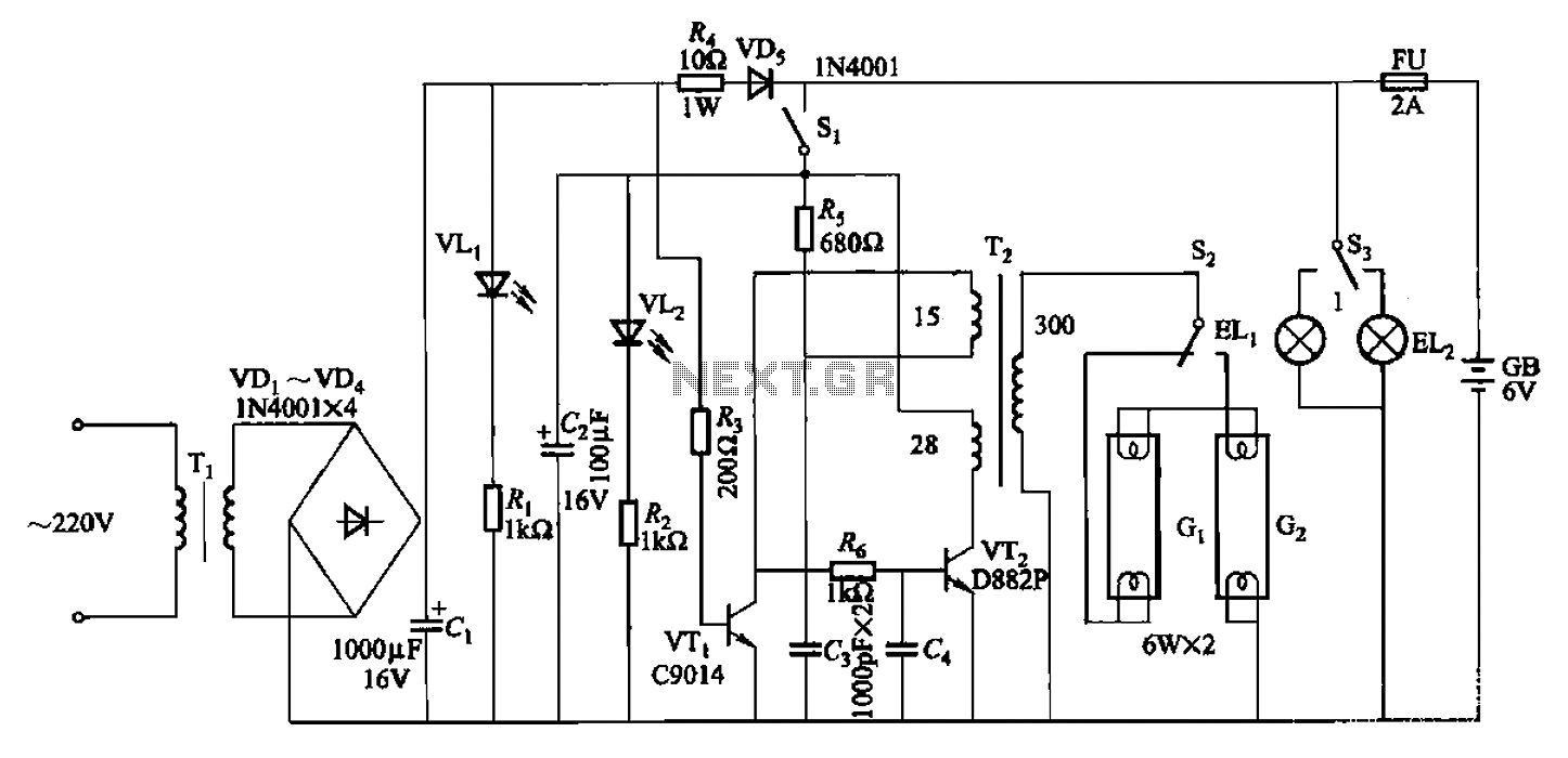
The 786A multi-functional double-tube fluorescent emergency circuit is illustrated in Figure 2-129. This circuit shares similarities with Figure 2-125. The 786A multi-functional double-tube fluorescent emergency circuit is designed to provide illumination during power outages or emergencies. It utilizes two fluorescent...
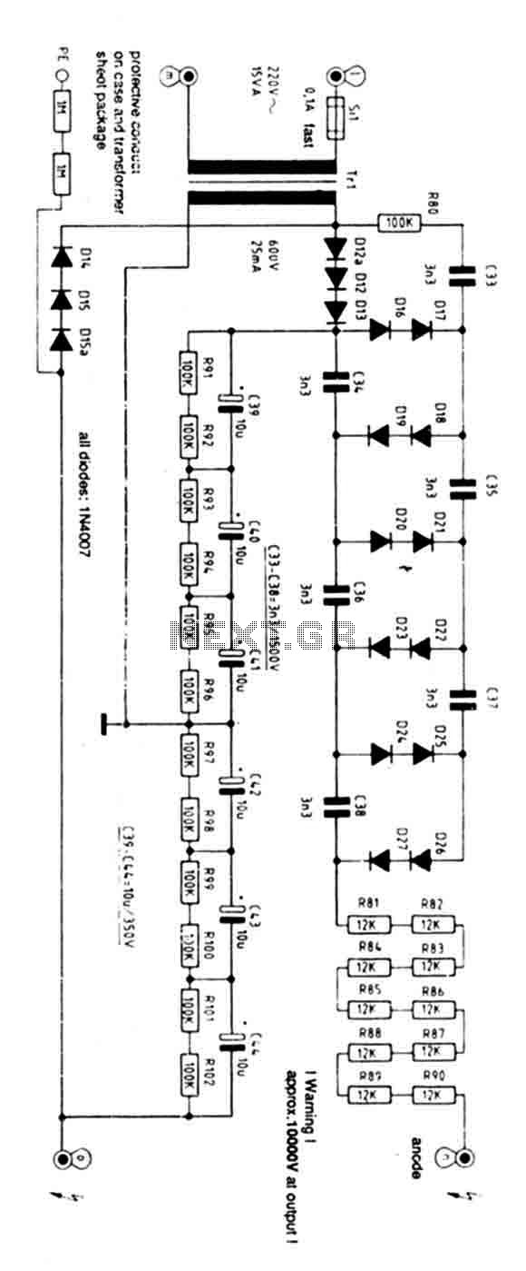
Exercise caution with this power supply as it operates on 220V mains and has an output voltage of 10KV. Characteristics: Supply: 220V AC 50Hz mains, Power: 15 Watts, Ignition Voltage: 8KV. The power supply operates on a standard 220V AC...
This document presents a very low-power monolithic 1.9GHz silicon Low Noise Amplifier (LNA) that operates with a total current consumption of 1.75mA, which includes the bias circuit. The described Low Noise Amplifier (LNA) operates at a frequency of 1.9GHz, making...