Joulethief SEC exciter and variants 68
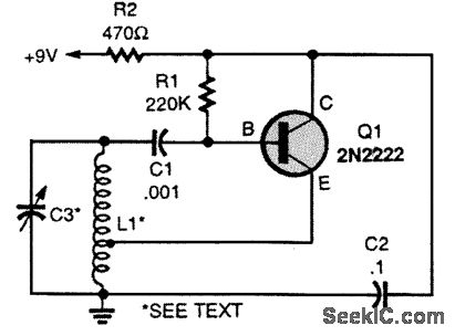
Design an efficient receiver/collector that can withstand a beam impact, potentially utilizing a large photomultiplier array. The system should employ a beam mode and wavelength that is not easily attenuated. In this scenario, explosive bursts from option 1 may be considered. Additionally, there is a reference to Tesla's later life, where he purportedly designed a beam device that produced a beam which decreased in size. Another consideration involves a special coil with a split secondary wound oppositely, which Tesla mentioned during one of his lectures. It is questioned whether this design serves as the foundation for coil type 1. If the magnetic fields oppose each other without a phase delay between the sides, it is suggested that discharging a capacitor into free air could occur with minimal current returning to the opposite side, and without oscillation due to the opposing magnetic fields.
Coil type 2, known as the Magnifier, differs in that each section is wound in opposite directions, but both sides of the secondary and extra coils are identical and opposite to the secondaries. The feasibility of transmitting power through the air is debated, with the notion that a beam or similar structure would be necessary between the transmitter and receiver, which may not be achievable with spherical antennas. An exception to this could be Tesla's concept of elevating spheres into the higher atmosphere.
A comparison is made between Tesla's bifilar wound coil in his patent and the top/bottom coils in the Kapagen device. Tesla's design connects them in series to achieve a voltage difference, whereas the Kapagen device winds them in clockwise/counterclockwise directions. In Tesla's method, the voltage difference between adjacent windings is distributed along the coil, whereas in the Kapagen device, it increases from the top to the bottom. The varying lengths of short coils in the Kapagen device suggest that this winding principle might be applicable at higher harmonics while still achieving voltage gain.
Tesla's winding method results in a cancellation of the magnetic field caused by currents through each half of the coil at half-wave resonance frequency, while Kapagen's design appears to maintain cancellation at multiple higher harmonics. This indicates that Kapagen's winding approach could produce a pure longitudinal electric oscillation across the coil windings without generating a magnetic field.
The energy created in a singular coil system is believed to be captured and utilized directly. Testing without spheres, using only ground connections to power loads, demonstrated good ground current with significant energy waste around the batteries. The conclusion drawn is that a larger capacitance than the batteries is necessary for effective energy storage, which would enhance ground currents and reduce waste, ultimately improving circuit efficiency.
An efficient receiver or collector designed for laser applications should incorporate robust materials capable of withstanding high-energy impacts from laser beams. The use of a photomultiplier array enhances sensitivity and allows for effective collection of light energy, especially when configured for optimal wavelength reception.
The system must be engineered to minimize energy loss, utilizing beam modes that are less susceptible to atmospheric attenuation. This may involve selecting wavelengths that can penetrate various environmental conditions without significant degradation. The implementation of explosive bursts in the design could serve as a method for generating high-intensity light pulses, potentially improving the energy capture efficiency of the system.
The coil design, particularly the special configuration referenced in Tesla's lectures, warrants detailed analysis. The opposing magnetic fields created by the split secondary winding can facilitate unique discharging characteristics, allowing for energy transfer without conventional oscillation. This principle can be further explored in the context of coil type 2, where the winding direction influences the overall electromagnetic behavior.
Incorporating Tesla's bifilar winding concepts alongside the Kapagen device's approach may yield innovative solutions for energy transmission. The comparative analysis of voltage distribution in these designs highlights the importance of winding techniques in achieving desired electrical properties.
Future designs should focus on optimizing the geometry and configuration of coils to enhance performance, particularly in applications involving wireless power transmission. The integration of advanced materials and technologies will be crucial in developing a system capable of efficiently harnessing and utilizing energy from laser sources while minimizing losses and maximizing output.Laser Design an efficient reciever/collector that could withstand a beam hitting it (maybe an enormous photomultiplier array ), and use a beam mode and wavelength that isn`t easily attenuated. And in that case you`d go for the explosive bursts of option 1. And didn`t Tesla later in his life announce that he had designed a beam device that produced a beam which grew
smaller And an other thing I was thinking about: Do you agree that the special coil with the split secondary wound oppositely, which was the ONLY one Tesla ever talked about (that I can find reference to), during one of his lectures, . do you think that is the basis for coil type 1 If the magnetic fields oppose each other, and there is no phase delay between the opposite sides, (in one type Eric seems to indicate there should be an odd phasing between the sides, because he shows a push-pull type setup for driving the primaries in one of his papers, but labels them as phases), and if the secondaries were connected in a certain way to the primaries, you could literally discharge the capacitor into free air with hardly any current actually discharging back to the other side of the capacitor, and it would happen WITHOUT oscillation due to the opposing magnetic fields.
(does that make sense ) I think with coil type 2 (Magnifier) the main difference is that each section of the coil is wound in opposite directions to the next, but each side is NOT a mirror- both sides of the secondary are wound the same, and both sides of the extra coils are the same, but opposite of the secondaries. You may be right that there are posiblities to transmit power trough the air, but you would somehow need to create a beam or something between transmitter/receiver, which I don`t see happening with spheres used as antenna.
Of course, there is one exception, invented by Tesla, which is to lift the spheres up into the higher atmosphere. What is interesting is to compare Tesla`s bifilar wound coil from his patent with the top/bottom coils in the Kapagen device.
As you can see, Tesla connected them in series, in order to get the voltage difference, while in the Kapagen device they are wound CW/CCW. So, with Tesla`s coil, the voltage difference between adjacent windings is distributed across the coil, while with the Kapagen device, this increases from top (connected part) to bottom.
Given that with the Kapagen device, we have different length short coils at the top and the bottom, this suggests that you probably may use this principle also at higher harmonics with the Kapagen way of winding and still get this voltage gain effect. You see, with Tesla`s way of winding, you only get the situation that the magnetic field caused by the currents trough each half of the coil cancel each other out at the half wave resonance frequeny (over the whole coil), while with Kapagen`s, they seem to always( ) cancel one another out, or at least at more than one higher harmonic.
So, it seems that with Kapagen`s way of winding, you can create a pure (longitudinal, "pressure-like") electric oscillation across the coil windings, without creating a magnetic field. Ok, so we are basically on the same page. I also believe the energy created in a singular coil system can be captured and used directly. I`ve also done this without the sphere`s and used a ground only to power the loads. But, the actual capacitance of the missing sphere is replaced by the batteries driving the system. The end result in my small test set up was there was good ground current and a lot of wasted energy being emitted around the batteries.
Still lighting FL`s very nicely around them and the circuit. My conclusion was that there needs to be a larger capacitance than the batteries as a storage in order to intensify the ground currents and thus remove the waste and make the circuit more efficient. Reminds me of t 🔗 External reference


