
Joulethief SEC exciter and variants1
The reference to Joseph Newman’s work suggests a focus on energy generation and conversion principles, particularly in the context of a specific graph that illustrates these concepts. Newman's theories often delve into unconventional energy sources and mechanisms that challenge traditional understanding of energy conservation and generation.
In an electronic schematic context, the graph might represent a circuit that demonstrates the relationship between input energy and output energy in a system, potentially highlighting the efficiency of energy conversion or the presence of additional energy sources. This could involve components such as capacitors, inductors, and energy storage devices, which play crucial roles in managing and transforming energy within a circuit.
The schematic may include a representation of various energy pathways, illustrating how energy is harnessed and utilized within a system. Key components could involve a power source, switches for controlling energy flow, and output devices that utilize the generated energy, such as motors or lights. Additionally, the circuit could feature feedback mechanisms that allow for the adjustment of energy output based on demand, showcasing a dynamic interaction between energy input and output.
Understanding the principles illustrated in the graph requires a comprehensive analysis of the circuit's design, including the arrangement and specifications of each component. The behavior of the circuit under different operational conditions can provide insights into the efficiency and effectiveness of the energy generation methods proposed by Newman, as well as their practical applications in modern electronic systems.Hi folks, Hi slayer. this graph from Joseph Newman`s book should explain some things, though the energy increase is probably from other additional.. 🔗 External reference
Related Circuits
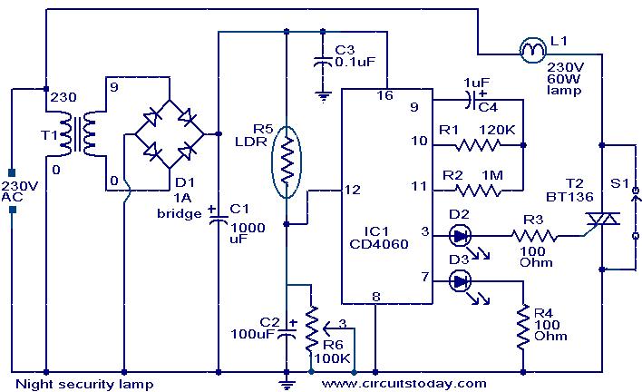
This simple circuit is built around a CMOS IC 4060 to obtain the required timing. During daytime, the LDR has low resistance and keeps pin 12 of IC1 high, preventing IC1 from oscillating. When it is dark, the LDR...
Repell those repugnant insects from your Garden this Summer with this insect repellant circuit. Designed by Graham Maynard, the circuitry consists of a phase locked loop (CMOS 4047) wired as a 22KHz oscillator. The output is amplified by a...
The EUA2032 is a high-efficiency, 2.5W mono class-D audio power amplifier. A newly developed filterless PWM modulation architecture further reduces EMI and THD+N, as well as eliminates the LC output filter, thereby reducing the external component count, system cost,...
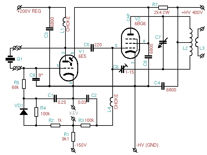
The installation of the 6E5 tube is straightforward, as its socket pinout closely resembles that of the common 6J5 and 6C5 triodes. This allows for a seamless replacement of these tubes with the 6E5 Magic Eye without the need...
The anti-theft system includes two frequency sirens connected to the vehicle's immobilizer system. In the laboratory simulation model, the changes in operating modes, siren activation, and fuel supply cut-off are indicated by the illumination of LEDs and communicated to...

This alarm features both open-loop and closed-loop detection systems along with an automatic alarm shutoff mechanism. It provides a 15-second delay for exit and entrance. Additionally, the alarm activation time can be adjusted from 1 to 15 minutes. The alarm...