
Night security light

The circuit employs a CMOS IC 4060, which functions as a timer and oscillator. The light-dependent resistor (LDR) is a crucial component that determines the circuit's response to ambient light conditions. During daylight, the LDR maintains a low resistance, resulting in a high voltage at pin 12 of IC1. This condition keeps the oscillator in a stable state, preventing it from generating output pulses.
As night falls and light levels drop, the resistance of the LDR increases significantly. This change causes pin 12 of IC1 to receive a low voltage, activating the oscillator. The output from pin 3 of IC1 is designed to go high after a predetermined period, specifically 8 hours, which is achieved through careful selection of the resistors R1, R2, and capacitor C4. This output serves to trigger a triac, which in turn powers a lamp, effectively illuminating the area at approximately 2 AM.
In the morning, as daylight returns, the resistance of the LDR decreases, bringing pin 12 of IC1 back to a high state. This action halts the oscillation, leading to the output at pin 3 returning to low, thus turning off the lamp. The inclusion of switch S1 provides a manual override, allowing the user to activate the lamp regardless of the ambient light conditions.
Additionally, capacitor C2 is integrated into the circuit to mitigate the risk of false triggering. This capacitor acts as a filter, smoothing out any rapid fluctuations in voltage that could inadvertently cause the triac to activate when it is not intended. Overall, this circuit design effectively combines light sensing, timing, and manual control to create a reliable automatic lighting system.This simple circuit is build around a CMOS IC 4060 to obtain the required timing. During day time the LDR has low resistance and keeps the pin 12 of the IC1 high, preventing the IC1 from oscillating. When it is dark the LDR resistance becomes high and the pin 12 of IC1 becomes low and the IC starts oscillating, which indicated by the flashing of L
ED D3. The values of the timing components R1, R2, C4 are so selected that the out put pin3 of IC1 goes high after 8 hours. That means the high output drives the triac to switch on the lamp around 2`O clock. At morning, the LDR resistance drops and the pin 12 of IC1 goes high and stops the oscillation, making the lamp OFF.
The switch S1 can be used to manually ON the lamp. The capacitor C2 prevents false triggering. 🔗 External reference
Related Circuits
The following circuit illustrates the CD4017 integrated circuit (IC) used in an automatic room lights sensor circuit diagram. Features include a single light sensor utilizing two light-dependent resistors (LDRs). The CD4017 is a decade counter IC that can drive multiple...
The circuit is designed to switch off a specific lamp or a group of lamps based on varying ambient light levels. Once constructed, it will turn off a lamp at dawn and turn it on at dusk. The power...
The circuit diagram presented is for an IC controlled emergency light with a charger, functioning as a 12V to 220V AC inverter circuit. Key features include automatic activation of the light during a mains failure and a battery charger...
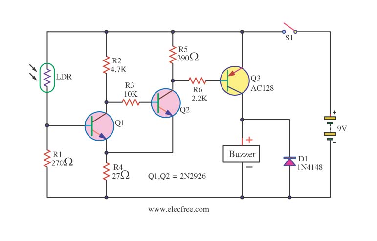
This circuit activates a warning when it becomes dark, functioning as a light-sensitive switch. The essential electronic components include the 2N2926 and AC128 transistors. The described light-sensitive switch circuit is designed to detect ambient light levels and activate an output...
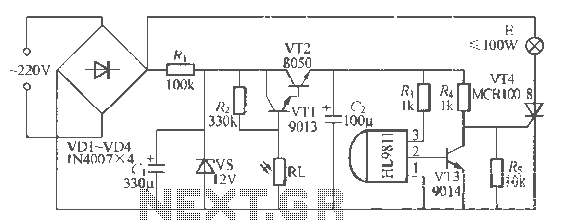
The H1.9811 single-channel flash control integrated circuit from Wuxi Love Core Microelectronics Co., Ltd. is designed for controlling flashing warning lights in road barricades. It features an integrated internal RC oscillator, frequency divider, output buffer amplifier, shaping circuit, and...
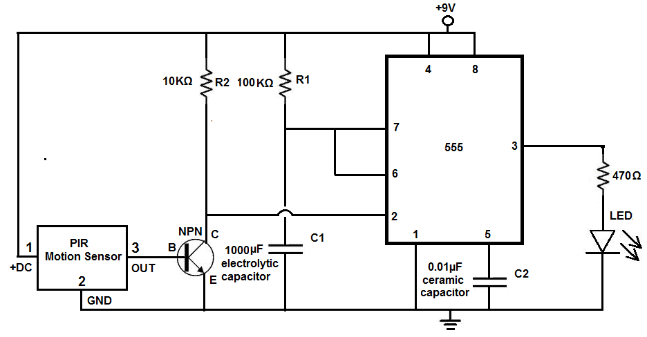
Many individuals install motion detectors in their backyards or homes to automatically turn on lights when movement is detected. Motion sensor lights have gained popularity and are increasingly utilized in various settings. Businesses frequently employ them in bathrooms, where...