
jtag cable
The JTAG (Joint Test Action Group) cable serves as a vital interface for programming and debugging embedded systems. The DB25 header connects to the parallel port of a computer, allowing for communication between the computer and the target device. This connection utilizes a standard protocol for debugging and testing, enabling the transfer of data and commands.
The 20-pin (or 14-pin) IDC header on the opposite end is designed to connect to the user's circuit board. This connection facilitates the integration of the JTAG interface into the target system. The wiring configuration of the 20-pin IDC header is critical for ensuring that the correct signals are transmitted to and from the target device. Each pin in the IDC header corresponds to specific functions, such as TCK (Test Clock), TMS (Test Mode Select), TDI (Test Data In), and TDO (Test Data Out), which are essential for JTAG operations.
The circuit diagram referenced in Figures 1 and 2 provides a visual representation of the connections and pin assignments for the JTAG cable. It is important to follow the specified wiring method to avoid miscommunication and ensure proper functionality during debugging and programming sessions. The design may also include additional components, such as resistors or capacitors, to stabilize the signal and improve reliability.
In summary, the JTAG cable is a critical tool for developers working with embedded systems, providing a straightforward means of connecting a computer to a target circuit board for programming and debugging purposes. The precise wiring and connection methods outlined in the accompanying circuit diagrams are essential for successful implementation.One end of JTAG Cable is a DB25 header used for connecting the parallel port of computer and the other end is a 20 pin (or 14 pin) IDC header used for connecting the user`s circuit board. Fig. 1 and Fig. 2 form a complete JTAG Cable circuit diagram. The diagram only shows 20 pin IDC wiring method. 🔗 External reference
Related Circuits
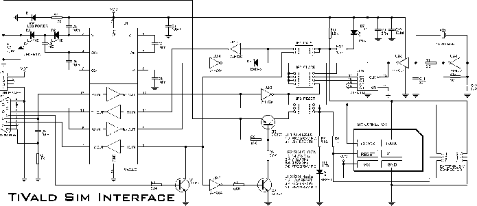
The electronic adapter derives its power supply from the VCC line of the smartcard reader device, or alternatively, an external 5 V supply can be utilized. The RST line of the card slot is connected to one of the...
The ML7005 is a multi-functional DTMF transceiver LSI that incorporates a DTMF signal generator, a DTMF signal receiver, a call progress tone generator, a call progress tone detector, and a FAX (FX) signal detector. Each functional block can be...
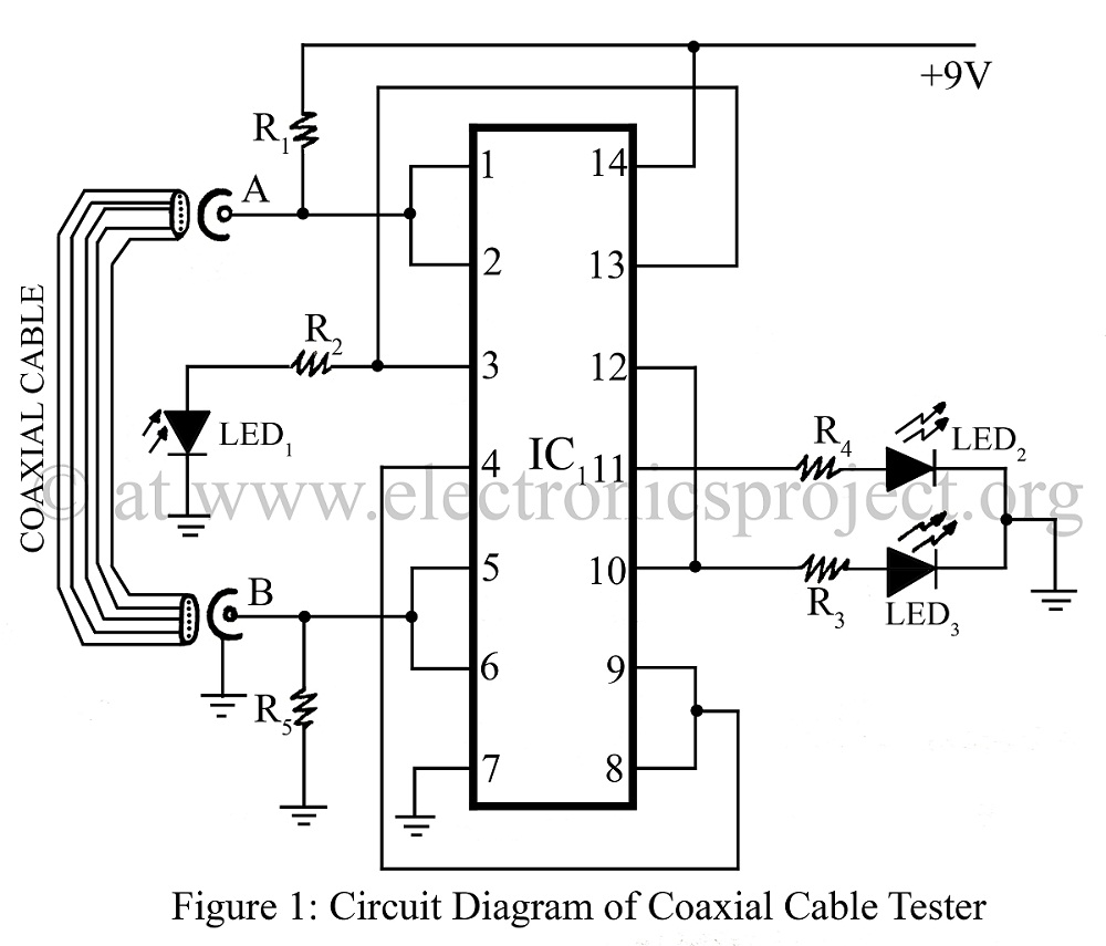
A coaxial cable tester is utilized to determine the condition of a coaxial cable, identifying whether it is open, short-circuited, or functioning correctly. This device employs a digital IC 4001 and includes a circuit description along with a parts...
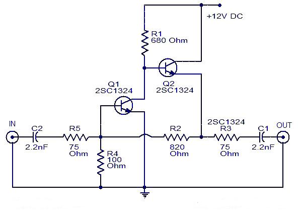
This is a cable TV amplifier utilizing two transistors. The amplifier circuit is designed for cable TV systems using 75 Ohm coaxial cables and operates effectively up to 150 MHz. Transistor T1 is responsible for amplification, providing an expected...
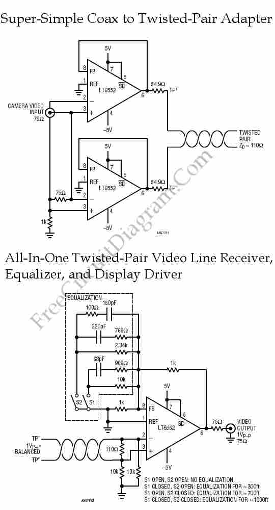
Twisted-pair wiring is a wiring technique commonly utilized for in-building data communication. Compared to conventional coaxial cable, this technique offers various advantages. Twisted-pair wiring consists of pairs of insulated copper wires that are twisted together to form a single cable. This...
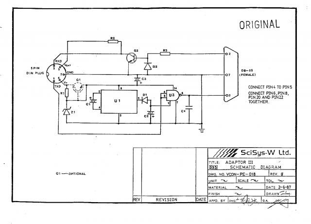
The SciSys Leonardo, Saitek Galileo, and Renaissance chess computers can be connected to a PC using an OSA-Link cable, which is necessary to operate the OSA-4-Arena software and other tools. However, this cable is no longer available. Detailed instructions...