
Keyer dimmer table lamp circuit

The keyer dimmer table lamp is designed to provide adjustable lighting through a user-friendly interface featuring two touch-sensitive buttons. The circuit operates on a capacitance buck converter principle, which allows for efficient voltage regulation and dimming capabilities.
The touch buttons serve as input controls; one button is designated for dimming the light, while the other increases the brightness. When the dimming button is activated, it triggers a reduction in the output voltage supplied to the lamp, causing the light to gradually weaken. Conversely, activating the brightness button increases the output voltage, resulting in a brighter illumination.
The circuit's core components include diodes VD1 and VD2, which are responsible for rectifying the AC input voltage to a suitable DC voltage level. The capacitors C2 and C3 play a crucial role in smoothing the rectified output, ensuring stable operation and minimizing voltage fluctuations. This arrangement allows for a seamless transition between different brightness levels, enhancing the user experience.
The overall design emphasizes efficiency and reliability, making it suitable for various applications where adjustable lighting is desired, such as in living rooms, bedrooms, or workspaces. The simplicity of the touch interface combined with the effective dimming mechanism offers a modern solution to traditional lamp controls.Keyer dimmer table lamp adopts two touch buttons to adjust the light. The light changes weaken from strong when peopletouch one of the buttons, and it changes strong from weaken when peopletouch the other button. Working principle The principle of this circuit is shown in diagram 1. Capacitance buckDC power supply is composed of VD1, VD2, C2 and C3.. 🔗 External reference
Related Circuits

A cell phone jammer is an electronic device designed to obstruct the transmission of signals between a cell phone and its nearby base station. By transmitting on the same frequency as cell phones, the jammer generates significant interference, disrupting...
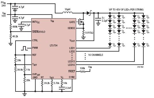
The LT3754 is a 16-channel LED driver featuring a step-up DC-DC controller developed by Linear Technology. It is designed to drive LEDs with a voltage of up to 45V. Each channel of the LT3754 LED driver is equipped with...
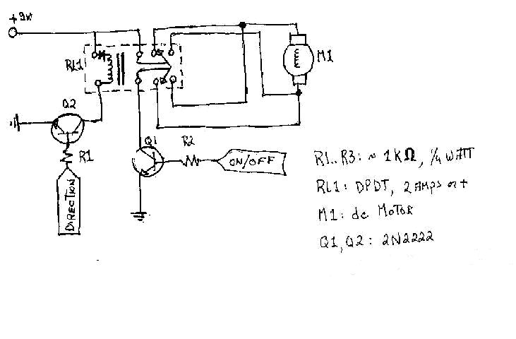
To create the circuitry described, a computer software capable of controlling a parallel port is required, with an estimated cost of approximately $30. For instance, a transistor (model number 2N2222) is priced around $0.50, while a DPDT relay costs...
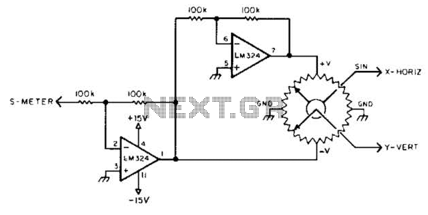
To display polar quantities, which include both the magnitude and direction of a received radio signal, a sine and cosine voltage proportional to an angle corresponding to the antenna direction is required. This setup utilizes a sine-cosine potentiometer connected...
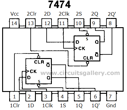
Digital counters have various applications in electronic circuits. In digital electronics, counters are utilized in different situations. This article presents the concept of a ring counter circuit, which functions as a register counter. An animation and simulation video of...

This generator circuit utilizes an overdriven amplifier to generate a 60 Hz square wave from the 60 Hz AC line. The circuit is suitable for line-operated applications as a clock source. The generator circuit operates by leveraging an overdriven amplifier...