
Pattern Generator For Radio Direction Finding Circuit

In this system, the sine-cosine potentiometer serves as a critical component that translates the angular position of the antenna into corresponding sine and cosine voltages. As the antenna is rotated to various positions, the potentiometer outputs vary, producing two voltage signals: one representing the sine of the angle and the other representing the cosine of the angle. These voltages are essential for determining the phase and amplitude of the incoming radio signal.
The directional antenna captures the radio waves, and the voltage sample derived from the received signal is processed to determine its magnitude. This voltage is usually scaled to ensure that it can be accurately compared with the outputs from the sine-cosine potentiometer. The combined information from the potentiometer and the received signal allows for a comprehensive representation of the signal's characteristics.
The display mechanism, which could be an analog or digital interface, presents the polar quantities visually, enabling users to assess both the strength and direction of the signal easily. This setup is particularly useful in applications such as radio direction finding, where understanding the orientation and intensity of signals is crucial for effective navigation and communication. In order to display polar quantities (magnitude and direction of a received radio signal), a sine and cosine voltage proportional to an angle (antenna direction) is needed. In this case, a sine-cosine potentiometer coupled to a directional antenna and a sample of a voltage proportional to received signal is used to display
relative magnitude and direction of a received signal.
Related Circuits
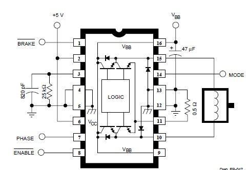
This simple DC servo motor circuit design can be utilized in various electronic projects. The circuit schematic illustrates that this DC servo motor driver employs a single integrated circuit along with a few external electronic components. For bidirectional DC...
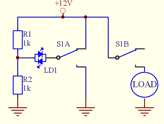
Assistance is needed for a project involving the construction of a switch panel. The individual has a good understanding of 12V electrical wiring but is encountering difficulties with this specific task. The project involves designing a switch panel that can...
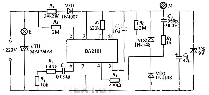
The BA2101 is a dimming controller utilizing an ASIC to create a barrel of light touch stepping. It is a non-constant lamp suitable for heir light. Each touch on the electrode sheet M can adjust the lamp brightness through...
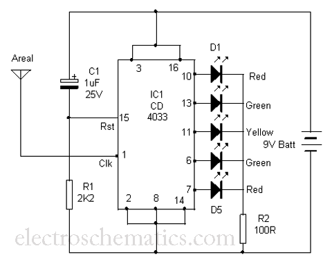
This is a simple tool designed to measure the level of radiation emitted by electrical or electronic devices. The circuit utilizes LEDs to create a running light pattern when it detects electromagnetic radiation from a source. It can detect...
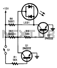
With switch SI open, base bias is supplied to transistor Q2 through a voltage divider formed by resistors R2 and R3, which activates the green element of the LED. This indicates that power is being supplied to the project....
The call is triggered by the position sensing circuit, which activates the control circuit and SOS alarm circuit. This system is designed for critically ill patients or to assist disabled individuals in the event of a fall. A position...