
Keypad Controlled Switch No2

The Keypad Controlled Switch No2 Circuit is designed to allow users to control a load through a keypad interface. The circuit utilizes a microcontroller or a dedicated keypad decoder to interpret the key presses. When a specific key is pressed, the microcontroller activates a relay, which in turn controls the power to the connected load.
The circuit typically includes the following components:
1. **Power Supply**: A voltage regulator may be used to ensure stable operation within the specified voltage range (5-15V).
2. **Keypad**: A matrix keypad is commonly employed, allowing for multiple key inputs while minimizing the number of input pins required.
3. **Microcontroller/Decoder**: This component processes the keypad inputs and controls the relay. It can be programmed to recognize specific key sequences for different functions, such as turning the load on or off.
4. **Relay**: A relay suitable for the chosen supply voltage is used to switch the load. The relay should be rated for the load current and voltage to ensure safe operation.
5. **Load**: The device or circuit that will be controlled by the relay, which could be anything from lights to motors.
The design considerations include ensuring that the relay's coil voltage matches the power supply voltage and that the microcontroller's output pins are capable of driving the relay, either directly or through a transistor for higher power applications. Additionally, debounce logic may be implemented in the software to prevent multiple activations from a single key press.
This circuit can be further enhanced with features such as LED indicators to show the status of the load or additional safety mechanisms to prevent unauthorized access or accidental activation.Keypad Controlled Switch No2 Circuit The circuit is drawn with a 12-volt supply - but it will work at anything from 5 to 15-volts. All you have to do is choose a relay suitable for the supply voltage you want to use. Replace the.. 🔗 External reference
Related Circuits
For hobbyists or professional electronic engineers engaged in various electronic experiments, troubleshooting, or testing, it is essential to provide a wide range of variable options. In electronic engineering, the ability to manipulate and measure a wide range of variables is...
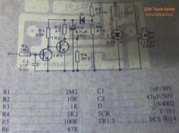
This circuit is a 220V AC lamp touch dimmer. By simply touching the dimmer, it is possible to adjust the light intensity of incandescent lamps in three stages. The touch dimmer utilizes an 8-pin CMOS IC, specifically the TT8486A...
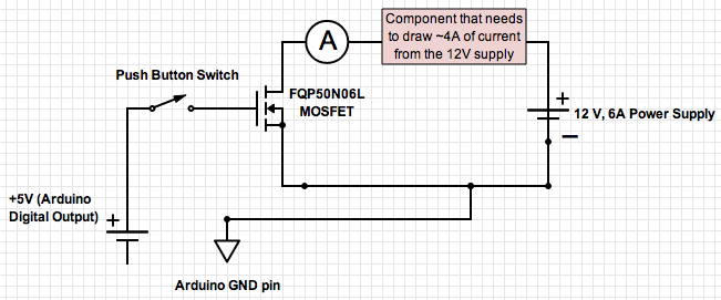
If the ground of the Arduino is disconnected from the negative terminal of the power supply, current flows through the MOSFET, even when the switch is not closed. In an electronic circuit involving an Arduino and a MOSFET, maintaining a...
The MC145152-2 synthesizer can be programmed using DIP switches, a diode matrix, or EPROM look-up tables. However, it is now difficult to find, costing around US$30. Modern synthesizers require PIC processors for programming or must remain connected to a...
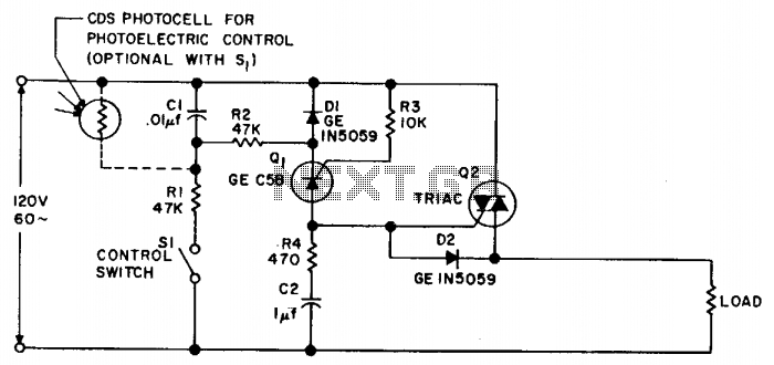
Synchronous switching activates only when the AC supply voltage crosses zero and deactivates only when the current reaches zero. This circuit responds to either a mechanical switch or a variable resistance, such as a cadmium-sulfide photocell. It minimizes disturbances...

The 2N4391 features a low ON resistance of 30 ohms and a high OFF impedance of less than 0 pF when in the off state. With appropriate layout and an optimal switch configuration, the stated performance can be easily...