
arduino Circuit with switching MOSFET not working

In an electronic circuit involving an Arduino and a MOSFET, maintaining a common ground reference is crucial for proper operation. The Arduino microcontroller typically requires a stable ground connection to function correctly. When the ground of the Arduino is disconnected from the negative terminal of the power supply, it creates a floating ground condition. This can lead to unexpected behavior in the circuit.
In this scenario, the MOSFET, which is a type of transistor used for switching or amplifying electronic signals, may still conduct current even when the control switch is open (not closed). This phenomenon occurs because the gate-source voltage (Vgs) may still exceed the threshold voltage (Vth) required to turn the MOSFET on, due to the floating ground. This can happen if there are stray voltages or capacitive coupling in the circuit, which can inadvertently turn on the MOSFET.
To prevent such issues, it is essential to ensure that all components in the circuit share a common ground. This can be achieved by connecting the ground pin of the Arduino directly to the negative terminal of the power supply. Additionally, careful circuit design should include decoupling capacitors and proper layout techniques to minimize noise and ensure stable operation. Implementing these practices will enhance the reliability of the circuit and prevent unintended current flow through the MOSFET when the switch is open.If I disconnect the ground of the Arduino from the negative terminal of the power supply, current flows through the MOSFET, even when the switch isn`t closed! 🔗 External reference
Related Circuits

The circuit involves a Signetic balance modem connection utilizing a transistor array as a phase detector. It provides information about the cosine of the phase angle, which corresponds to the frequency of the input signal combined with the integrated...
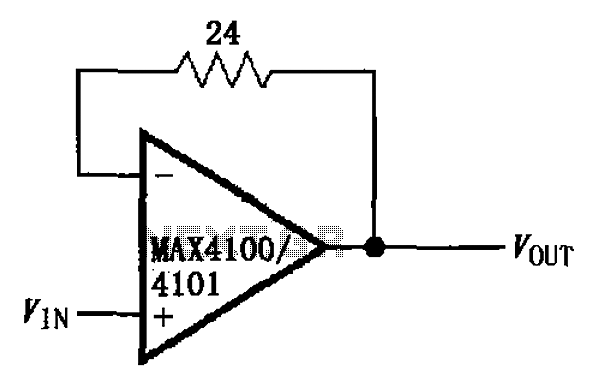
The circuit illustrated is a unit gain buffer circuit utilizing the MAX4100/4101 operational amplifiers. It incorporates a small resistor (24 ohms) within the feedback loop of the amplifier, thereby establishing a unity gain buffer. This configuration maximizes the bandwidth...
This circuit illustrates the LM2576T integrated circuit (IC) step-down switching power supply circuit diagram. Features include a 60V input voltage with output options of 3.3V, 5V, 12V, and 15V. The LM2576T is a popular voltage regulator known for its ability...

CMOS switches are utilized to select entries in audio circuits. While these switches can introduce unacceptable levels of distortion, incorporating them into the feedback network of an operational amplifier (op amp) can effectively minimize this distortion. The circuit employs...
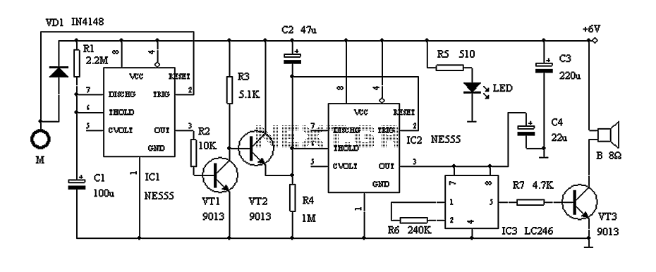
This circuit describes a door alarm system equipped with a time recognition feature. When the owner opens the door, it remains in a normal state for approximately 30 seconds without triggering the alarm. However, if the door is opened...
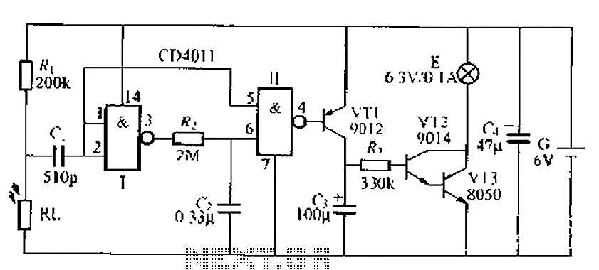
A battery-powered light control circuit is designed to delay the lighting of a small lamp during sudden power outages or nighttime situations when a blown fuse leaves a room in darkness. This circuit addresses the difficulty of locating matches...