
Knight Rider Lights


This setup is ideal for running off a car battery.
The circuit described utilizes a 555 timer configured in astable mode, which generates a continuous square wave output. This output serves as a clock signal for the CD4017 decade counter, which counts the pulses and activates its outputs sequentially. The 10K resistor connected between the output of the 555 timer and the clock input of the 4017 ensures that the pulses are appropriately limited in amplitude, preventing damage to the IC from excessive current.
The CD4017 has ten output pins (Q0 to Q9), each capable of driving a load. In this application, LEDs are connected to these outputs. Since certain LEDs need to remain illuminated for multiple counts, diodes are employed to ensure that current flows only in the desired direction, thus preventing any potential short circuit that could arise from multiple outputs being activated simultaneously.
To ensure the counter resets to zero upon power-up, a capacitor and resistor are connected to the reset pin (pin 15) of the 4017. This configuration allows the capacitor to charge and subsequently reset the counter, ensuring reliable operation from the moment power is applied.
For applications requiring higher power outputs, the ULN2001N Darlington driver IC can be utilized. This IC can drive larger loads, such as 12V bulbs, by providing sufficient current gain. Each output of the ULN2001N can be activated by a low-level signal from the CD4017, making it suitable for controlling higher voltage devices without directly interfacing with the low-voltage logic levels of the CD4017.
Overall, this circuit is particularly well-suited for battery-powered applications, such as automotive lighting systems, where the 12V bulbs can be directly powered by the outputs of the ULN2001N, creating a versatile and efficient lighting solution.The 555 timer IC is connected for Astable Operation, the clock pulses are fed to the 4017 IC via the 10K resistor. The 4017 is a 10 stage counter, each of the outputs is connected to the appropriate LED, as some LEDs need to be on for more than one count, we use diodes to avoid a short circuit situation between outputs.
The capacitor and resistor on pin 15 of the 4017 are used to reset the counter to zero at initial power up. The ULN2001N used on the bulb version is a seven channel Darlington Driver IC, a small signal on one of the inputs is enough to drive the bulb on the output.
You can use 12V bulbs for the output, simply substitute the IC for the LEDs, the bulbs are then connected to the IC's outputs. This set up is ideal for running off a car battery. 🔗 External reference
Related Circuits
This device functions as a simple timer that keeps the vehicle's headlights on for approximately 1 minute and 30 seconds, allowing access to dark areas without the need to return and switch off the lights. Pressing switch P1 enables...
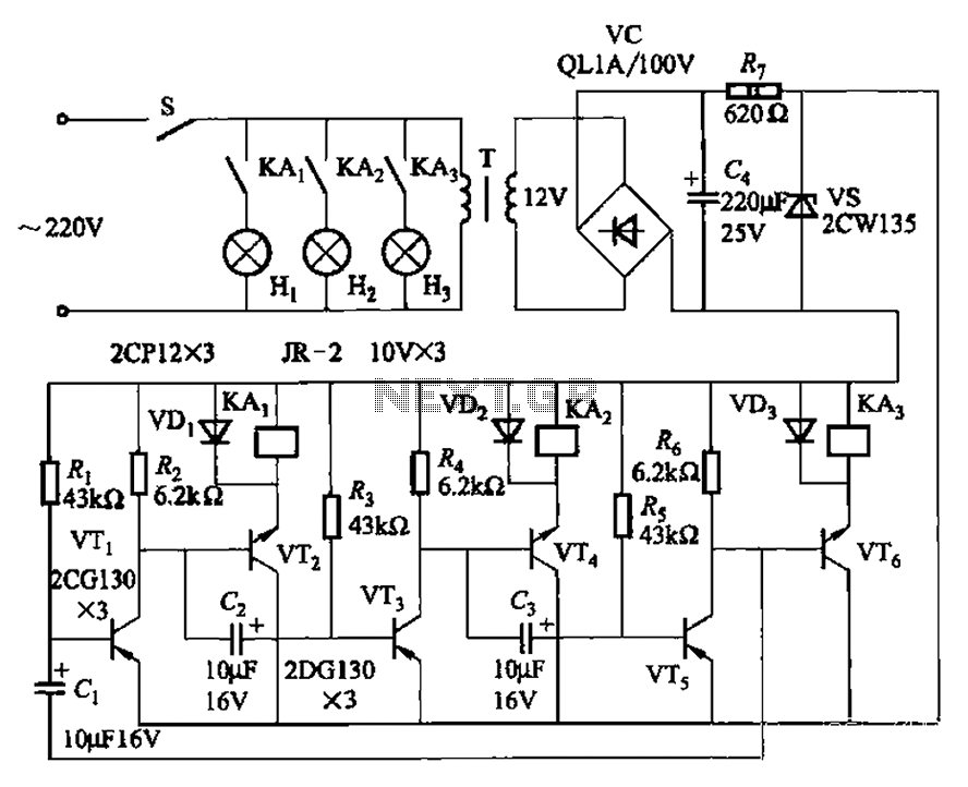
The transistors VTi, VT3, and VTs, along with the RC components, form three distinct multi-resonator oscillators. The oscillation frequency levels are dependent on the values of Ri, R3, Rs, and Cl, as well as Cz and C3s. The circuit comprises...
This circuit is designed to drive a total of 42 LEDs, assuming a forward voltage of approximately 2.2V per LED and a forward current of around 21mA for adequate brightness. If the specifications of the LEDs differ significantly, modifications...
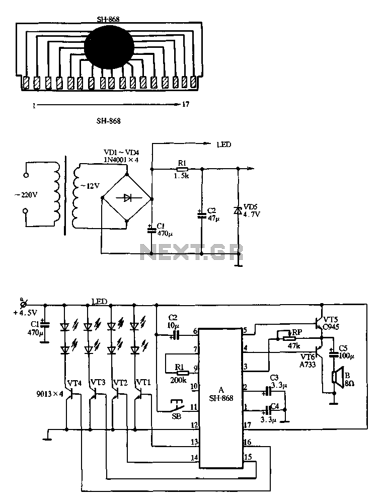
Figure 2-80 illustrates the SH-868, an integrated circuit designed for a music flash circuit powered by three batteries. It can drive a flashing light-emitting diode (LED) while simultaneously activating a sound speaker. The device features a function selection button...
The system operates solely on vacuum. Upon inspection of the vacuum hoses, two brittle hoses were found that ran through the firewall to the headlight switch, where a slight hissing sound was noticeable when the lights were activated. Touching...
This circuit gradually switches the internal lights of a car on and off. The delay time can be adjusted by changing the values of the 10k and 4.7M resistors, as well as the capacitor. The circuit operates by utilizing a...