
Knightrider lights for model cars

The circuit operates by sequentially illuminating the LEDs to create a scanning effect reminiscent of the iconic "Knightrider" car. The core component of this circuit is the 7555 timer IC, which is configured in astable mode. This configuration allows the timer to generate a continuous square wave output that drives the LEDs.
The circuit typically consists of six LEDs arranged in a line. Each LED is connected to a current-limiting resistor to prevent excessive current flow, which could damage the LEDs. The output from the 7555 timer is connected to a series of transistors or directly to the LEDs, depending on the design, allowing for the sequential lighting of the LEDs.
The frequency of the LED scanning effect can be adjusted by changing the values of the resistors and capacitors connected to the 7555 timer. By selecting appropriate resistor and capacitor values, the timing intervals can be modified to create different scanning speeds.
Additionally, the choice of LEDs impacts the overall power consumption of the circuit. Different LED types have varying forward voltages and current requirements, which should be taken into account when designing the circuit.
In summary, this circuit provides an engaging visual effect through the sequential illumination of LEDs, driven by a 7555 timer IC, with power consumption influenced by the LED selection and circuit configuration.This simple circuit drives 6 LEDs in `Knightrider scanner mode`. Power consumption depends mainly on the type of LEDs used if you use a 7555 (555 CMOS version) 🔗 External reference
Related Circuits
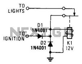
A relay and two diodes are all that is needed; the relay performs the job of a buzzer, so no annunciator is required. When the lights are left on while the ignition is off, the normally closed relay contacts...

The turn signals, hazard lights, stop lights, and headlights are functioning properly. However, the tail lights do not operate when the headlights are on. The bulbs appear to be in good condition, as they were tested by switching the...

It utilizes the mains supply through a basic DC rectifier circuit. The circuit operates by converting alternating current (AC) from the mains supply into direct current (DC) using a rectifier. A typical implementation involves a bridge rectifier configuration, which consists...
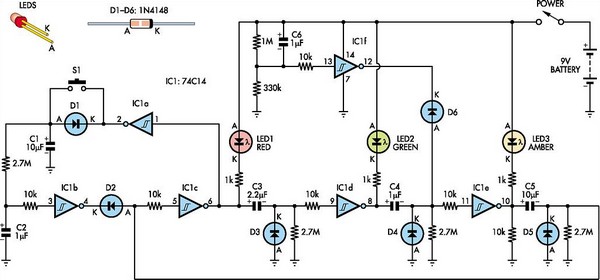
This toy traffic signal utilizes a single, cost-effective hex Schmitt-trigger inverter IC (IC1a-IC1f) to directly control three colored LEDs (red, green, and amber). Upon activation, the circuit illuminates the red signal for 30 seconds, followed by the green signal...

The circuit activates a light corresponding to the first button pressed in a "Who's First" game. Three stages are illustrated, but the circuit can be expanded to accommodate any number of buttons and lamps. The described circuit operates as a...
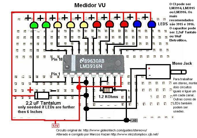
A post related to a do-it-yourself project for creating a VU meter and homemade rhythm lights that are easy to assemble. The project involves designing and constructing a visual audio level meter (VU meter) that responds to sound levels, as...