
become a VU meter and homemade rhythm lights easy [megapost]
![become a VU meter and homemade rhythm lights easy [megapost]](/uploads/25/LM3916schematics.jpg "become a VU meter and homemade rhythm lights easy [megapost]")
The project involves designing and constructing a visual audio level meter (VU meter) that responds to sound levels, as well as rhythm lights that flash in sync with music or audio signals. The VU meter can be created using a microcontroller, such as an Arduino, which processes audio input and drives LED indicators to reflect the amplitude of the sound.
To begin, the circuit requires an audio input source, which can be connected via a 3.5mm audio jack. An operational amplifier (op-amp) can be used to amplify the audio signal before it is fed into the microcontroller's analog input pin. The microcontroller will then convert the analog signal into a digital value, allowing it to determine the sound level.
For the visual output, a series of LEDs can be arranged in a bar graph format. Each LED will represent a different level of audio intensity, with the microcontroller controlling which LEDs are illuminated based on the processed audio signal. The code running on the microcontroller will include algorithms to smooth out the signal and provide a more visually appealing response, such as fading effects or dynamic flashing patterns.
In addition to the VU meter, the rhythm lights can be implemented using a similar approach. By utilizing a separate set of LEDs, the circuit can be designed to flash in response to specific frequencies or beats detected in the audio input. This can be achieved through frequency analysis, where the audio signal is processed to identify peaks in specific frequency ranges, triggering the corresponding lights to flash in rhythm with the music.
Overall, this DIY project combines basic electronics, programming, and audio processing to create an engaging visual display that enhances the experience of listening to music. The simplicity of the components and the accessibility of microcontrollers make this project suitable for hobbyists and beginners in electronics.Post related to Do it yourself about become a VU meter and homemade rhythm lights easy.. 🔗 External reference
Related Circuits
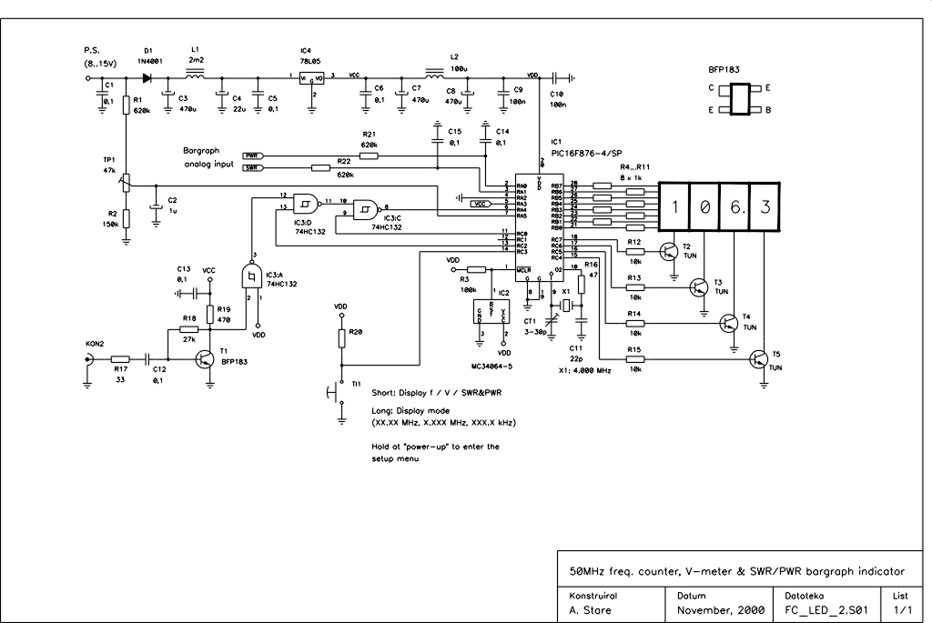
This device is an upgraded version of the PIC16C71 4-digit LED frequency counter and voltmeter. It eliminates several hard-to-find components from the previous model, which have been out of production for some time. The older PIC16C71 has been replaced...
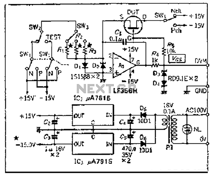
Chen is in the operational amplifier circuit, utilizing a feedback loop with input resistance that determines the current roll-off. The FET drain current is controlled by the determination circuit, which provides the necessary voltage. The output constitutes a fake...
If this picture above looks a lot like the Pretty Good LC Meter also on this web site, that's because it's the same meter, but with some significant improvements. At this point, it's a good idea to read the...

This circuit utilizes two quad voltage comparators, specifically the IC LM339, to illuminate a series of eight LEDs that indicate volume levels. Each of the eight comparators is biased at increasing voltages set by a voltage divider, allowing the...
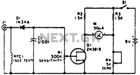
This circuit employs a FET as a DC amplifier within a bridge configuration. Resistor R4 is adjusted for meter nulling with switch J1 short-circuited. Any surplus 50-mA meter can be utilized in this circuit. RFC1 represents a suitable RF...
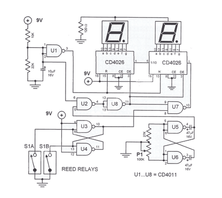
This digital DIY tachometer for bicycles utilizes two reed switches to obtain speed information. The reed switches are positioned near the rim of the wheel. The digital DIY tachometer circuit is designed to provide accurate speed measurements for bicycles by...