
Knightrider lights for model cars

The described circuit utilizes a 7555 timer IC configured in astable mode to create a sequential LED lighting effect reminiscent of the "KITT" scanner from the television series Knight Rider. This effect is achieved by driving six LEDs, which are connected in series or parallel configurations depending on the desired visual effect and power requirements.
In the astable configuration, the 7555 timer generates a continuous square wave output, which can be adjusted for frequency by varying the resistor and capacitor values connected to the timing pins. The output from the timer drives a series of transistors or MOSFETs, which act as switches for the LEDs, allowing them to turn on and off in succession.
The circuit design should include appropriate current-limiting resistors for each LED to prevent excess current from damaging them. The power consumption of the circuit is influenced by the forward voltage and current specifications of the LEDs used, as well as the supply voltage provided to the 7555 IC.
It is essential to ensure that the VDD (positive supply voltage) and GND (ground) connections for the 7555 IC are correctly established to ensure proper functionality. These connections are typically made to a DC power source, which can vary depending on the specifications of the LEDs and the requirements of the circuit.
The overall layout of the circuit should be carefully planned to minimize interference and ensure a reliable operation of the LED scanning effect. Proper grounding and decoupling capacitors may also be added to enhance stability and performance, especially if the circuit is implemented in a noisy electrical environment.This simple circuit drives 6 LEDs in `Knightrider scanner mode`. Power consumption depends mainly on the type of LEDs used if you use a 7555 (555 CMOS version). Note that VDD and GND for the ICs are not shown in the circuit drawing. 🔗 External reference
Related Circuits
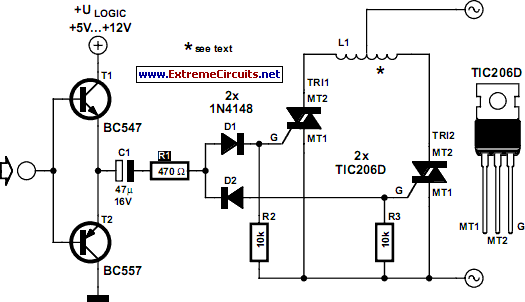
This compact circuit is designed to control model railway turnouts that operate using AC voltages. A control signal within the range of 5 to 12 volts can be utilized. The turnout coils are activated by triacs. Variations in the...
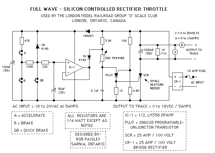
It was designed for use on a The London Model Railroad Group's large O scale layout located at London, Ontario, Canada. The prime requirements for the club throttles were that they be rugged, reliable and produce as little heat...
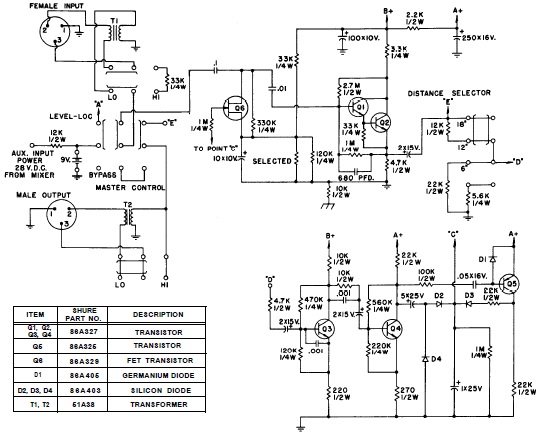
SHURE is an American corporation that manufactures consumer and professional audio electronics, including microphones, phonograph cartridges, and discussion systems. SHURE Incorporated is a well-established entity in the audio electronics industry, recognized for its innovative design and high-quality products. The company...
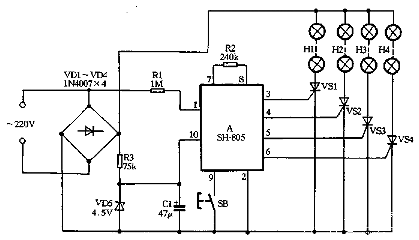
The SH-805 circuit serves as a holiday lights controller, as illustrated in Figure 2-64. It is similar to the SH-804 circuit board, although the pin locations and control functions differ. By pressing the SB button, users can select between...

Most cars lack delayed interior lights. The presented circuit addresses this issue by gradually switching the interior lights on and off. This feature facilitates activities such as locating the ignition keyhole after the car door has been closed. The...
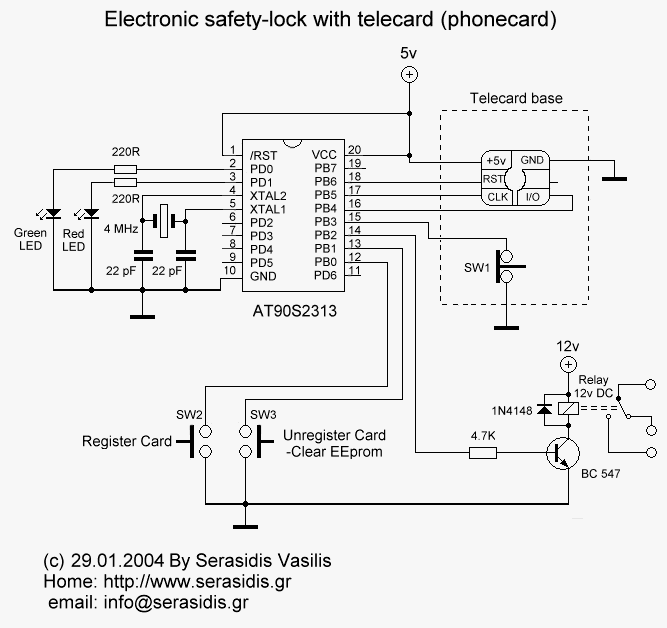
Most of the source code for this project is based on the Telecard reader project from my website. The components are few and ordinary, which means they are low-cost and easy to find. The "keys" are empty or non-telecards...