
Model Railroad Group SCR Throttle

The electronic circuit described is a robust and efficient throttle design intended for model railroading applications, specifically tailored for a large O scale layout. The circuit is engineered to deliver a continuous current of 5 amps and a maximum voltage of 18 volts DC. This capability is essential for ensuring that the model trains can operate smoothly and reliably under varying load conditions.
At the core of this design is a Programmable Unijunction Transistor (PUT) that plays a critical role in triggering a Silicon Controlled Rectifier (SCR). The PUT is utilized due to its ability to generate a precise timing pulse that ensures the SCR is activated at the appropriate moment in each cycle of the full-wave DC supply. This method of operation not only enhances the efficiency of the circuit but also minimizes voltage drop across the SCR, leading to reduced power loss and heat generation.
The choice of components and the circuit topology are aimed at achieving high durability and reliability. The ruggedness of the design is crucial for its application in a club environment where multiple users may operate the throttles simultaneously. Continuous operation since 1987 demonstrates the effectiveness of the design and its components in meeting the demands of model railroad enthusiasts.
In summary, this throttle design exemplifies a well-engineered solution for model railway applications, combining efficiency, reliability, and minimal thermal output, making it suitable for long-term use in a communal setting.It was designed for use on a "The London Model Railroad Group`s" large O scale layout located at London, Ontario, Canada. The prime requirements for the club throttles were that they be rugged, reliable and produce as little heat as possible.
Throttles of this type have been in service at the club since 1987 with excellent results. The throttle will deliver 5 amps continuously and up to 18 volts DC. See Notes. The Programmable Unijunction Transistor used to trigger the SCR is the key to this design as it ensures that the SCR fires on every cycle of the fullwave DC. This gives a very efficient operation with low voltage loss and very little heat generated. Pleas 🔗 External reference
Related Circuits
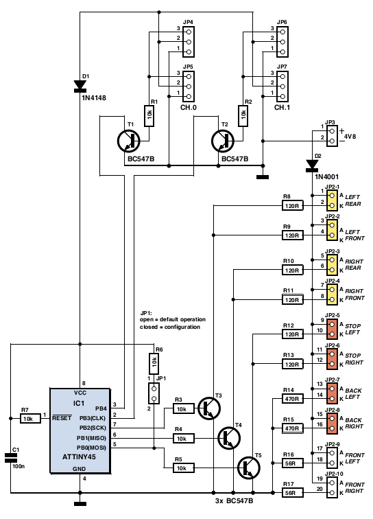
The author gifted a radio-controlled (RC) model car to his partner. She enjoyed it but suggested that adding realistic lights would enhance the experience. Consequently, the author returned to his workshop, utilized his soldering iron, and began outfitting the...
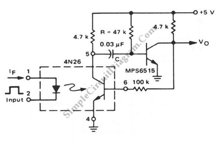
This is a pulse stretcher circuit utilizing an optocoupler. The circuit employs a 4N26 optocoupler in conjunction with a standard one-shot circuitry. The pulse stretcher circuit is designed to elongate the duration of an incoming pulse signal, which is particularly...

The ability of an SCR to control large currents to a load using a small gate current makes the device highly useful in switching and control applications. Several potential applications for the SCR include power control, switching, zero-voltage switching,...
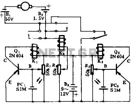
In the absence of light, photocells PC1 and PC2 exhibit high resistance, causing transistors Q1 and Q2 to remain off, which prevents the relay contacts K1 and K2 from closing. The battery B3 is connected through a potentiometer Rs,...
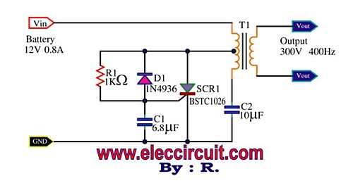
This is a Mini Power Inverter that utilizes SCR as the main electronic component. It operates an oscillator generator at 400Hz, providing an output of 300V from a 12V input voltage. The Mini Power Inverter is designed to convert a...

The circuit comprises a launch timer and an automatic-off timer. Upon applying power to the integrated circuit (IC), the countdown LED sequence activates until all LEDs are illuminated. When the last LED (LED1) is fully lit, transistor Q1 enters...