
L200 Variable Voltage Regulator

The L200 is a versatile adjustable voltage and current regulator that can deliver a wide range of output voltages and currents. It features an internal reference voltage and can be configured to provide constant voltage or constant current outputs based on the application requirements.
The circuit typically includes a few essential components: the L200 IC itself, input and output capacitors for stability and filtering, and resistors to set the desired output voltage and current limits. The configuration of the resistors connected to the feedback pin of the L200 allows for the adjustment of the output voltage. Additionally, a current-sensing resistor can be placed in series with the load to monitor and limit the output current.
The input voltage to the L200 should be higher than the desired output voltage, taking into account the dropout voltage of the IC. Adequate heat sinking may be required depending on the output load to prevent thermal shutdown of the device.
In practical applications, the circuit can be used for powering various electronic devices requiring specific voltage and current levels, such as battery chargers, power supplies for sensors, and LED drivers. The flexibility of the L200 allows for easy adjustments and modifications to meet varying operational demands.
Overall, the L200-based variable regulator circuit is an efficient solution for applications requiring precise control over voltage and current, making it a popular choice among electronic engineers and hobbyists alike.The circuit diagram of the circuit variable regulator, which uses IC L200, as regulator of voltage and current, IC For this comes from the company .. 🔗 External reference
Related Circuits
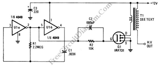
The schematic diagram below illustrates a circuit for a high voltage generator. This circuit employs a 4049 hex inverter as an oscillator, and it can be utilized for ignition purposes. The high voltage generator circuit is designed to convert a...
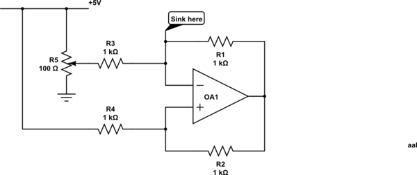
Control a current through several current-mirror devices (specifically the IREF pin on the TLC5940) using a single potentiometer. A modified Howland current source has been utilized, which works adequately with the specified resistor values for dimming an LED. However,...
This is a simple, precise voltage-controlled current source. Bipolar supplies will allow for bipolar output. Configurations that include a grounded voltage-control source and a grounded load tend to be more complex and rely on several components for stability. In...
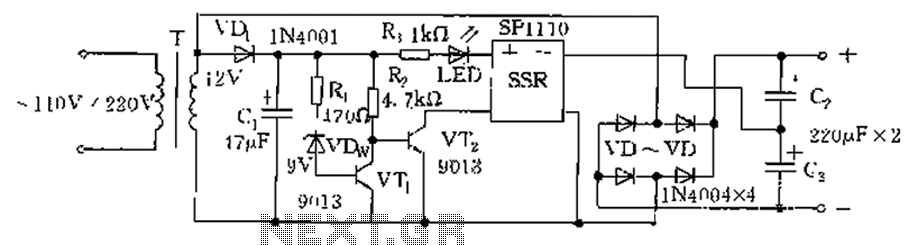
The circuit is automatically converted to a low-voltage configuration. A 220V AC supply is stepped down by transformer T. After this, the breakdown voltage of diode VDw causes transistors VT1 and VT2 to turn off, resulting in the solid-state...
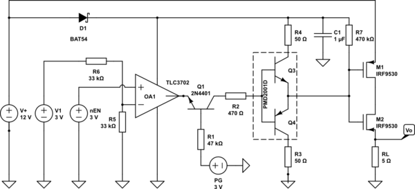
A battery switch-over circuit is being developed, consisting of two parallel lanes as depicted in the circuit diagram. The operational voltage range spans from 3V to 12V. Only one lane should be active at any given time, which is...
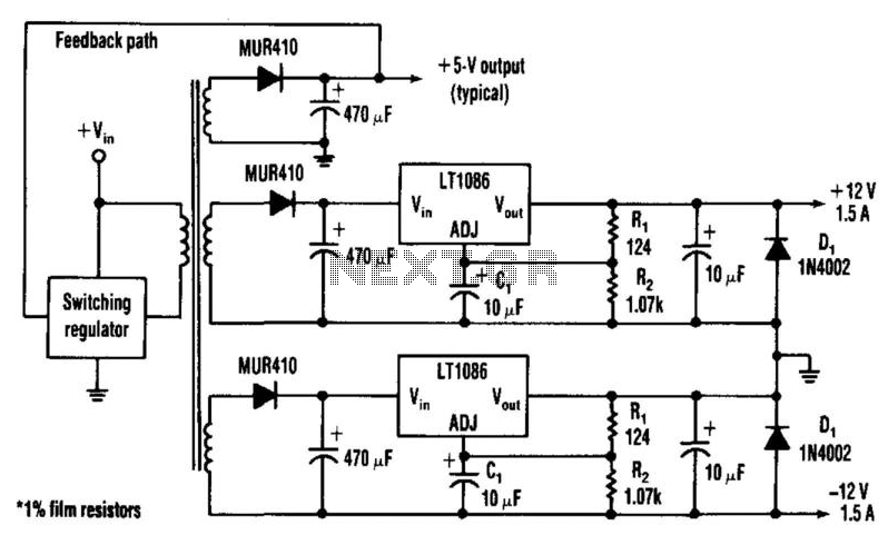
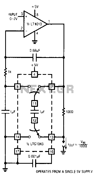
Many applications require highly efficient negative-voltage post regulators with low dropout voltage in switch-mode supplies. A method to achieve effective negative-voltage regulation is by utilizing a low-dropout positive-voltage regulator that operates from a well-isolated secondary winding of the switch-mode...