
Undervoltage lockout for small-power MOSFET gate driver

The battery switch-over circuit is designed to ensure seamless transition between two power sources while maintaining a stable output voltage. The circuit employs two lanes, each featuring a pair of p-MOSFETs configured in a back-to-back arrangement. This configuration allows for effective isolation and switching between the two battery sources, thus preventing reverse current flow and ensuring that only one battery is connected to the load at any given time.
The operational voltage range of 3V to 12V provides flexibility for various applications, making the circuit suitable for use in battery-powered devices. The logic control, although not detailed in the schematic, is critical for determining which lane is enabled based on the voltage levels of the connected batteries. This logic could be implemented using a microcontroller or dedicated logic circuitry that monitors the battery voltages and activates the appropriate lane.
Powering the switch-over circuitry and drivers through Vs, which is derived from the combined output of the batteries via diodes, allows for efficient utilization of the available battery power. However, careful consideration must be given to the scenario where Vs falls below 3V. At this threshold, the voltage approaches the safe operating limit for the gate of the p-MOSFETs, which is calculated as twice the gate threshold voltage (2 x Vg, th = 3V). Additionally, the TLC3702 comparator, which is likely used for voltage monitoring or control, has a minimum operating voltage that must not be exceeded to ensure reliable performance.
To mitigate potential issues arising from low Vs conditions, it may be beneficial to implement additional circuitry that monitors the voltage and provides feedback to the logic control. This could involve using a voltage divider or a dedicated voltage supervisor IC that can trigger a switch-off or lane change before the voltage drops to critical levels. By incorporating these features, the reliability and efficiency of the battery switch-over circuit can be enhanced, ensuring consistent operation across its specified voltage range.Developing a battery switch-over circuit which is made of two lanes of the depicted circuit. Operation voltage range is from 3V. 12V. Only one lane should be enabled at a time which is governed by logic not included in the schematic. Each lane can (dis)connect its battery (V+) by means of two back-to-back p-MOSFETs (Vg, th = 1. 5V). The drivers and switch-over circuitry are powered by Vs which is derived by OR-ing all batteries via diodes. Now I am concerned over the case when the Vs voltage falls below around 3V which comes close to the MOSFETs safe (2x Vg, th) gate threshold voltage and the TLC3702 comparator minimum operating voltage. 🔗 External reference
Related Circuits
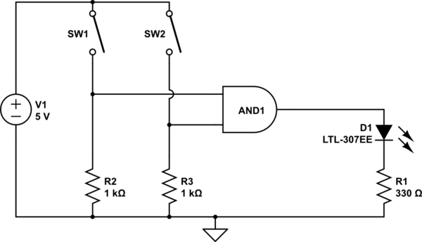
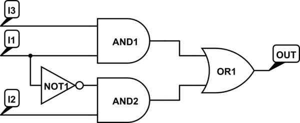
The AND output will be high when both switches are closed. However, there is no assurance regarding the input levels when the switches are open, resulting in unpredictable outcomes. In an electronic circuit utilizing an AND gate, the operation is...
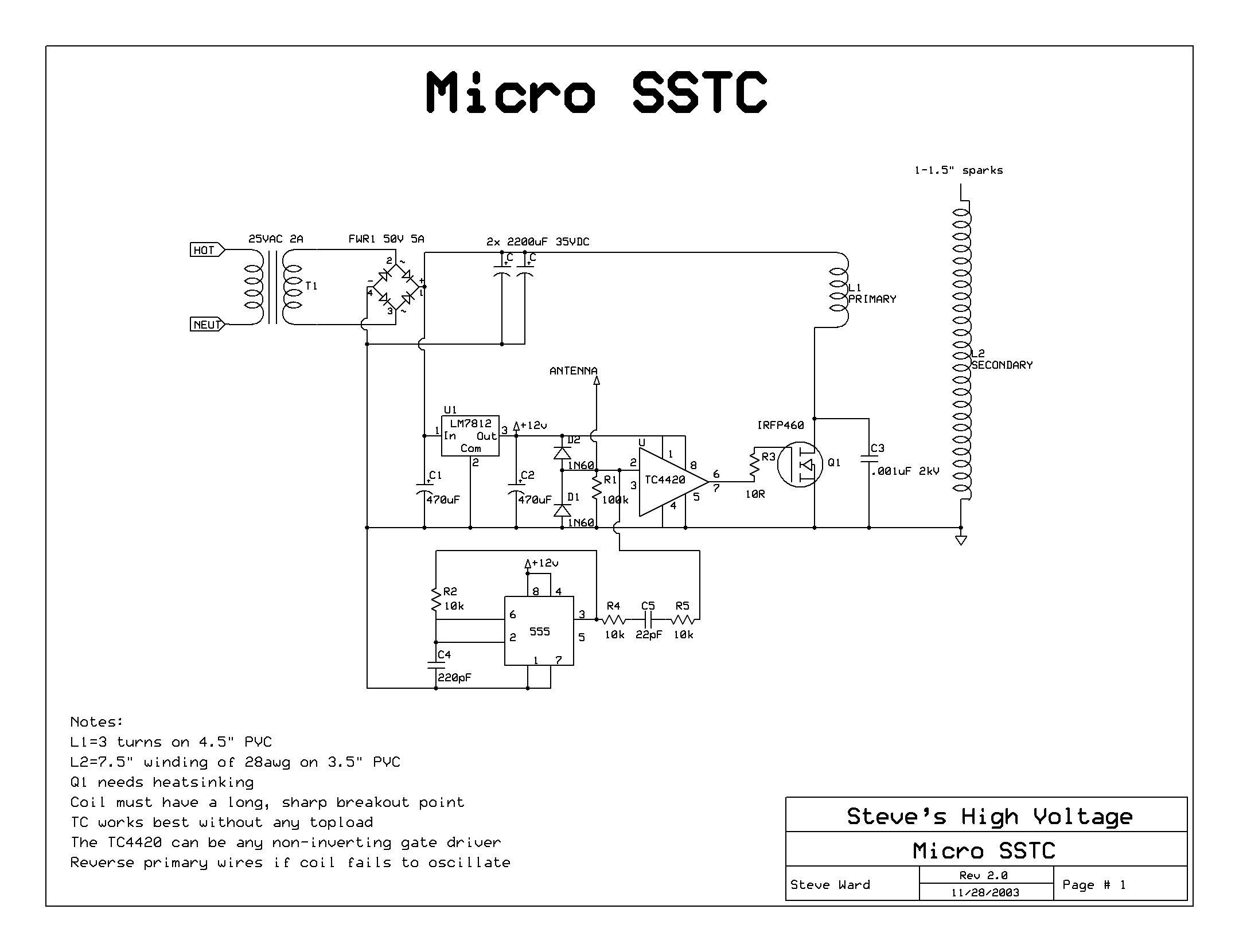
A solid-state flyback driver based on a micro solid-state Tesla coil circuit created by Steve Ward. The schematic is reprinted here with credits to Steve Ward. Instead of an air-core Tesla Coil setup, a flyback transformer is utilized. An...
One still designing that it uses in the exit transistor of technology V-mosfet. This transistors to us offer a lot of virtues concerning the simple bipolar transistors, as high speeds, thermic stability, low distortion etc. Beyond this circuit use...
L293D Schematic diagram. The L293D division supplies power to the chip and its controlled motors, enabling the connection of motors with a higher voltage power supply than the chip itself. The separation of power circuits and electric motors may...
There are integrated circuits that contain AND, OR, and NOT gates. The inquiry revolves around the existence of a single chip that encompasses all the required logic gates. If such a chip does not exist, specific alternatives should be...
The LT1206 is designed to drive multiple video cables, featuring a bandwidth of 60 MHz, an output current capability of 250 mA, and low output impedance. The LT1206 operational amplifier is optimized for video signal applications, making it an excellent...