
LA4555 Audio Amplifier

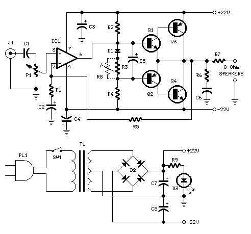
The LA4555 audio amplifier is an integrated circuit designed for audio amplification in consumer electronics. It features a dual-channel output, making it suitable for stereo applications, while also providing the option for mono operation. The amplifier can output 2.3 watts per channel into a 4-ohm load, which is ideal for driving small speakers in portable devices or compact audio systems.
The schematic typically includes input and output connections, power supply requirements, and component values such as resistors and capacitors that are essential for proper operation. The power supply voltage range for the LA4555 usually falls between 7V to 15V, allowing for flexibility in various applications. The circuit is designed to minimize distortion and maximize audio fidelity, making it suitable for a range of audio applications from televisions to portable music players.
In the stereo configuration, two LA4555 chips may be used to drive left and right channels independently, while in mono mode, a single chip can be configured to combine signals for a single output. The design may also incorporate additional features such as volume control, tone adjustment, and protection circuitry to prevent damage from short circuits or overheating.
Overall, the LA4555 amplifier is a robust solution for audio amplification, providing a balance of performance and efficiency in a compact form factor.LA4555 Audio Amplifier Stereo circuit and mono circuit are given in schematic .LA 4555 is basically a stereo amplifier with 2.3 watts into 4 ohms speakers at a total dis.. 🔗 External reference
Related Circuits
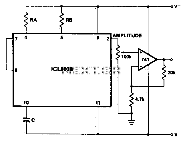
The sine wave output has a relatively high output impedance (1K typical). The circuit provides buffering, gain, and amplitude adjustment. A simple operational amplifier follower could also be used. The described circuit is designed to generate a sine wave output...
An inverting mode amplifier is required for precision accelerometers due to their typical charge output characteristics. This amplifier is utilized to convert charge into voltage. An inverting mode amplifier is a critical component in applications involving precision accelerometers, which often...
To configure the amplifier, set resistor R1 to its maximum value and resistor R12 to zero. After this adjustment, power on the amplifier. Adjust R1 until the measured output offset is between 30 mV and 100 mV. Once this...
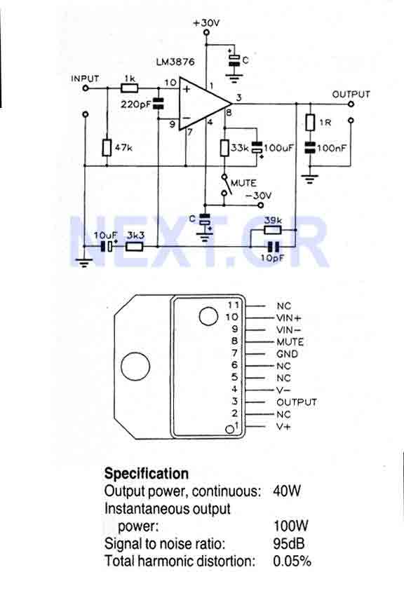
This Circuit is based on the LM3876. A 11-pin plastic package IC with high performance audio power amplifier, an output mute function which can be used to eliminate switch-on and switch-off "thumps" to the loudspeaker load. It is capable...
The external audio spectrum display circuit is designed for high-end audio equipment, providing both real-time playback signal analysis and visually appealing effects. This display does not require any electrical connections to the sound equipment; it can simply be placed...
This is a circuit schematic diagram for a power amplifier utilizing the IC TLE2141C. The TLE2141C is a low-noise, high-voltage, high-slew-rate operational amplifier. It offers a frequency response from 30 Hz to 20 kHz with a variation of 1...